A visual test device used for low-temperature liquified gas

A low-temperature liquefied gas and test device technology, which is applied to measuring devices, material analysis through optical means, instruments, etc., can solve problems such as limited visual range, inability to meet experimental needs, and inconvenient use, so as to improve the heat preservation effect and achieve good results. Designed for portability and improved visibility

Active Publication Date: 2016-11-09
NORTH CHINA UNIVERSITY OF TECHNOLOGY
View PDF4 Cites 9 Cited by
  • Summary
  • Abstract
  • Description
  • Claims
  • Application Information

AI Technical Summary

Problems solved by technology

[0005] In order to overcome the deficiencies of the prior art, the present invention provides a visual test device for low-temperature liquefied gas, which solves the problems of limited visual range, inconvenient use and inability to meet the experimental requirements of the existing test device

Method used


Image

  • A visual test device used for low-temperature liquified gas
  • A visual test device used for low-temperature liquified gas
  • A visual test device used for low-temperature liquified gas

Examples


Embodiment 1

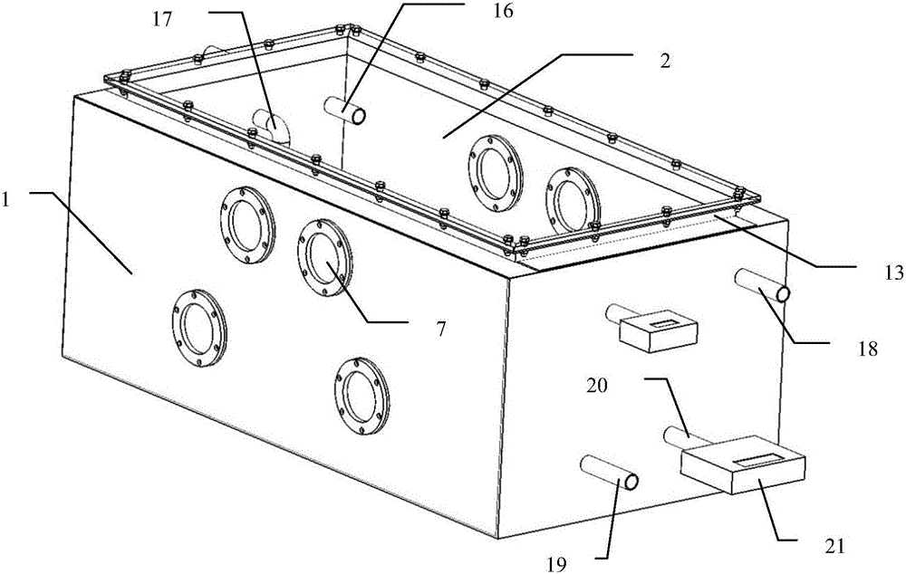
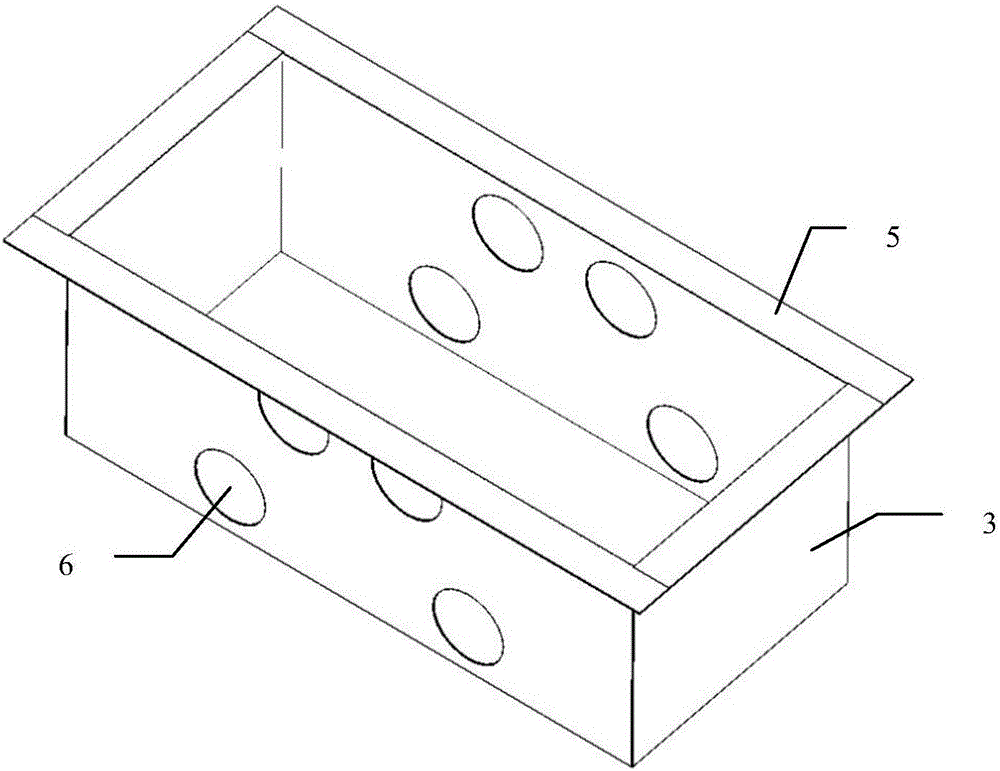
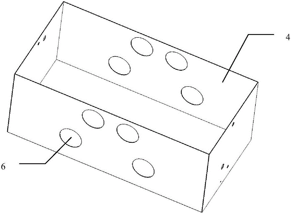
[0033] refer to Figure 1-5 , the preferred embodiment 1 of the present invention provides a visual test device for low-temperature liquefied gas, comprising a cuboid-shaped tank body 1 with an upper opening and a cover plate 2, and the tank body 1 includes an inner tank body 3 and an outer tank body 4 , the middle of the inner tank 3 and the outer tank 4 is provided with an insulating layer, and the four side tops of the inner tank 3 are bent outward at 90 degrees to form the top surface 5 of the tank, and the cover plate 2 is a transparent cover plate and sealed Installed on the top surface 5 of the tank body to form a top observation window; the front and rear sides of the inner tank body 3, the insulation layer and the outer tank body 4 are provided with a number of installation holes 6, and the front and rear sides of the tank body 1 pass through the installation holes 6 A side viewing window 7 is installed, and the side viewing window 7 includes an outer flange 8 on the ...

Embodiment 2

[0044] refer to Image 6, the preferred embodiment 2 of the present invention provides a visual test device for cryogenic liquefied gas, the only difference between it and embodiment 1 is that the structure of the side viewing window 7 is different, the side viewing window of this embodiment will be connected with the outer flange The connected transparent glass window is arranged as a concave transparent window 23, and its concave bottom surface, that is, the visible surface parallel to the inner transparent glass window, is as close as possible to the transparent glass window on the inner flange, and the fixed concave transparent window 23 The end cover is provided with a see-through plate 22, and the see-through plate 22 and the concave see-through window 23 form an internal sealed space, which can be vacuumed or filled with an inert gas. The cable is connected to an external monitor.

[0045] In this embodiment, the distance between the external window and the internal wi...

Embodiment 3

[0047] refer to Figure 7-8 , the preferred embodiment 3 of the present invention provides a visual test device for low-temperature liquefied gas, the only difference between it and embodiment 1 is that one or two side observation windows are replaced with the side heating windows of the cost embodiment, that is, the In the above-mentioned side heating window, the transparent glass window connected with the outer flange is set as a concave transparent window 23, and the transparent glass window connected with the inner flange is replaced with a heater, and the heater includes a right-side closed Heat conduction cylinder 26, the circumferential side of the heat conduction cylinder 26 is evenly provided with a number of heat conduction fins 28, the inside of the heat conduction cylinder 26 is provided with a heat collector 27, the heat collector 27 is connected to the heating fin 29, and the heating fin 29 passes through The connecting wire in the connecting pipe 30 is connected...


PUM


Abstract

A visual test device used for low-temperature liquified gas is provided. The visual test device includes an inner tank body, an insulating layer, an outer tank body and a cover plate. Tops of four side surfaces of the inner tank body are bent outwards by 90 degrees to form a tank body top surface. The cover plate is a transparent cover plate and is mounted in a sealed manner at the tank body top surface to form a top observation window. Front and back side surfaces of the inner tank body, the insulating layer and the outer tank body are provided with a plurality of mounting holes. The front and back side surfaces of the tank bodies are mounted with side observation windows through the mounting holes. The two sides of the test device are provided with the eight observation windows so that situations in the test device can be observed dynamically, and the large observation window is designed at the top, and therefore the inside of the test device is visual in a three-dimensional manner and the visual range is greatly increased.

Description

technical field [0001] The invention relates to the technical field of low-temperature liquid experiments, in particular to a visual test device for low-temperature liquefied gas. Background technique [0002] Industrial gas is the "blood" of modern industry, and its application covers many important fields such as iron and steel, metallurgy, chemical industry, shipbuilding, automobile, medicine, food, electronics, petroleum, aerospace and so on. With the rapid economic development, the demand for industrial gases is also surging. Liquid nitrogen and liquid oxygen are two cryogenic liquids commonly used in industrial production. With the wide application of clean energy, the application of these two cryogenic liquids in the national economy is becoming more and more extensive. [0003] Existing containers for cryogenic liquids such as liquid nitrogen, liquid oxygen, and liquid hydrogen are mostly used for storage and transportation, and experimental devices for experimental...

Claims


Application Information

Patent Timeline
Patent Type & Authority Applications(China)
IPC IPC(8): G01N21/84G01N25/00
CPCG01N21/84G01N25/00
Inventor 刘东徐宏海刘润一
Owner NORTH CHINA UNIVERSITY OF TECHNOLOGY
Why Eureka
Try Eureka