Nuclear reactor power monitor

Inactive Publication Date: 2013-08-15
KK TOSHIBA
View PDF1 Cites 3 Cited by
  • Summary
  • Abstract
  • Description
  • Claims
  • Application Information

AI Technical Summary

Benefits of technology

[0016]The present invention provides the technique for controlling nuclear power plant in which the thermal limit can be approached close to the full limit of operation restrictions by the automatic control, using the simple information outputted shorter cycle than that of the thermal limit.
[0017]FIG. 1 is a schematic diagram showing an embodiment of the nuclear power plant controlling system according to the present invention.
[0018]FIG. 2 is a horizontal sectional view of the nuclear reactor applied to the embodiment of the present invention.
[0019]FIG. 3 is a block diagram of the nuclear power plant controlling system concerning to an embodiment.
[0020]FIG. 4 is an explanatory view of the automatic control by the nuclear power plant controlling system concerning to an embodiment.
[0021]FIG. 5 is a flow chart explaining operation of the nuclear power plant controlling system concerning to an embodiment.

Problems solved by technology

Thus, it is necessary for the automatic control of the reactor power to observe the thermal limit continuously, but it is difficult because the calculation of the power distribution is required several minutes as mentioned above.

Method used


Image

  • Nuclear reactor power monitor
  • Nuclear reactor power monitor
  • Nuclear reactor power monitor

Examples


first embodiment

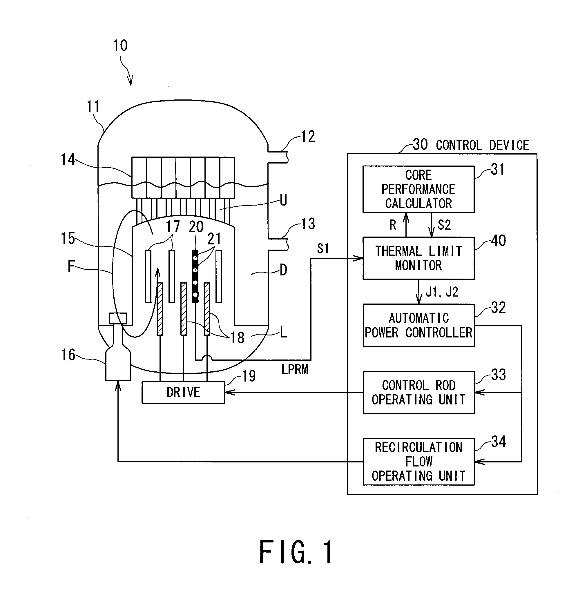
[0022]As shown in FIG. 1, nuclear reactor 10 includes, a reactor core 15 for heating a furnace water held at pressure vessel 11, a steam-water separator 14 for separating the heated furnace water into a steam and a fluid, a main steam line 12 for leading the separated steam to a turbine (not shown), a feed water line 13 for returning a feed water back to the pressure vessel 11 the feed water derives from the steam which worked and expanded in the turbine and then cooled and condensed, a recirculation pump 16 for circulating the furnace water with predetermined core flow F through a downcomer D, a lower plenum L, and a top plenum U the furnace water composed the separated fluid and the feed water joined.

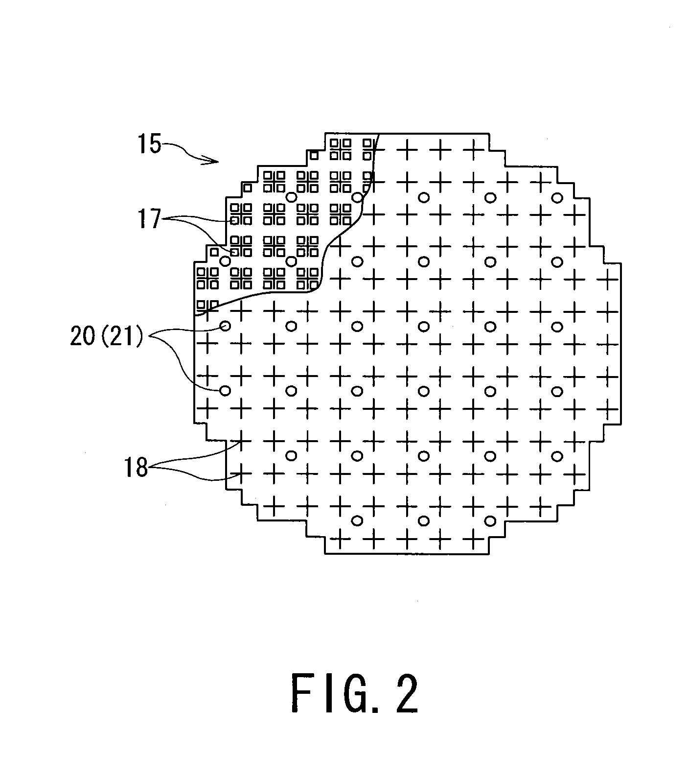
[0023]As shown in FIG. 2, horizontal sectional view of the reactor core 15 is composed of multi-arranging parts such as, a fuel assembly 17 consist of plurality of fuel rods (not shown) stored in a rectangular pipe-like channel box, a control rod 18 for adjusting number of neutrons by...


PUM


Abstract

Provide the technique for controlling nuclear power plant in which the thermal limit can be brought close to the full limit of operation restrictions by the automatic control, using the simple information outputted shorter cycle than that of the thermal limit.
The thermal limit monitor 40 includes: a first signal receiver 41 for receiving a first signal S1, a prospective time deriving unit 45 for deriving a prospective time f for the first signal S1 to arrive at a full limit G, a judging unit 46 for judging a remaining time to the prospective time f breaks a preset value m and then request a second signal S2 (outputs a request signal R), a compensating unit 44 for compensating the first signal S1 based on the second signal S2 received by the request, a first instruction transmitter 50 for transmitting a first instruction J1 to vary a rate factor of the first signal S1 and the second signal S2 with synchronizing the compensation; and a second instruction transmitter 51 for transmitting a second instruction J2 to hold the first signal S1 or the second signal S2 after arriving at the full limit G or a threshold K which right before the full limit G.

Description

TECHNICAL FIELD[0001]The present invention relates to the controlling nuclear power plant technology by observing a thermal limit.BACKGROUND ART[0002]In the boil water type nuclear power plant, the thermal limit such as the minimum critical power ratio and maximum linear heat generation ratio which is an indicator of the soundness of fuel is operated and managed so as not to exceed the full limit. These thermal limits calculated by the power distribution based on reactor physics are made to be observable object substitute for the surface temperature of the fuel since it is difficult to measure directly.[0003]These thermal limits are calculated by numerical analysis from distribution of a nuclear reaction cross section, and are calculated with the cycle of several minutes-1 hour by the reactor core performance calculation system with advanced operation throughput.[0004]In advanced boiling water reactor power plant, in order to attain and adjust the target reactor power, it is automat...

Claims


Application Information

Patent Timeline
Patent Type & Authority Applications(United States)
IPC IPC(8): G21C7/36
CPCG21C17/10G21D3/001G21C7/36G05B23/0235Y02E30/40Y02E30/30Y02E30/00G21C17/00G21C17/108
Inventor MASUGI, TSUYOSHISUZUKI, KIYOTERUYOSHINAGA, SURMANKOIZUMI, ATSUHIKO
Owner KK TOSHIBA
Why Eureka
Try Eureka