Method and apparatus in a pneumatic material conveying system

a conveying system and pneumatic material technology, applied in ventilation systems, lighting and heating apparatuses, heating types, etc., can solve problems such as nuisances, noise problems, dust problems and fine particles, which are perceived as unpleasant, and achieve the effect of reducing the nuisance of the outlet air, reducing the noise nuisance of the prior art, and reducing the noise nuisan

Active Publication Date: 2013-08-15
MARICAP OY
View PDF22 Cites 5 Cited by
  • Summary
  • Abstract
  • Description
  • Claims
  • Application Information

AI Technical Summary

Benefits of technology

[0011]The solution according to the invention has a number of important advantages. With the solution according to the invention, it is possible to essentially reduce the odor nuisances of the outlet air by adding air to the body of outlet air. By forming a chamber from an outer pipe arranged at least around the outward blowing end of the outward blowing pipe, a flexible solution for an apparatus, which is also very suited for manufacturing, is achieved. By shaping the shape of the outer pipe and / or the outward blowing end of the outward blowing pipe, the mixing effect and / or the suction effect of the additional air of the apparatus can be influenced. The apparatus can also be used for removing odors from a waste station or waste room. By directing or diffusing the air flow in the proximity of the output aperture, the perceived odor nuisance can be further reduced. With the solution according to the invention, the noise problem of prior art can also be essentially reduced. By arranging an ejector device in connection with the pipe for outlet air, the operating medium of which ejector device is the blowing air, extremely effective importing of additional air into the body of outlet air is achieved. By arranging a number of outward blowing pipes adjacently into a group, flow speeds can be boosted as a result of the combined effect of their blowings and a more effective suction effect on the additional air can be achieved. This further enhances the mixing of additional air into the blowing air. The mixing of additional air can be arranged according to one embodiment of the invention in a number of phases.

Problems solved by technology

In partial-vacuum conveying systems there are typically noise problems, as well as dust problems and fine particle problems, in the outlet pipe.
Especially in waste-conveying systems odor nuisances, which are perceived as unpleasant, often occur in the outlet air.
These have functioned fairly well, but they require a certain type of partial-vacuum generator, which is not necessarily suited to all waste-transporting systems.

Method used


Image

  • Method and apparatus in a pneumatic material conveying system
  • Method and apparatus in a pneumatic material conveying system
  • Method and apparatus in a pneumatic material conveying system

Examples


Embodiment Construction

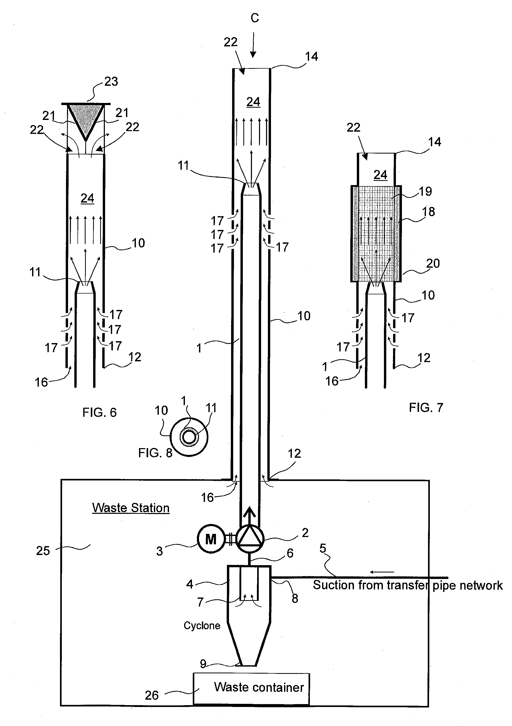
[0026]FIG. 1 presents a simplified view of one solution of an embodiment of the invention.

[0027]The outward blowing pipe 1 of the pneumatic pipe transport system for wastes is only partially presented in the figure. A second pipe part, i.e. an outer pipe 10, is arranged around the outward blowing pipe 1. The outer pipe 10 in FIG. 1 is a straight pipe part, the first end 12 (the bottom end in the figure) of which extends from the outward blowing end 11 of the outward blowing pipe 1 to some extent towards the input direction of the outlet pipe, i.e. in the opposite direction with respect to the input direction of the gases of the outlet pipe. The second end 14, i.e. the top end in FIG. 1, of the outer pipe extends a distance from the outward blowing end 11 of the outward blowing pipe 1 in the main blowing direction (upwards in FIG. 1) of the gases of the outward blowing pipe. Tie parts 13 are arranged between the outward blowing pipe and the outer pipe. In the embodiment of FIG. 1, th...


PUM


Abstract

Method for handling outlet air in a pneumatic waste-conveying system, in which the outlet air is at least partly the conveying air to be used in waste conveying. The outlet air is blown from the outward blowing pipe (1) into a chamber (24) comprising at least one output aperture (22) and one second aperture (16, 17), in which second aperture a suction effect is achieved with the blowing of the outlet air such that additional air is brought into the body of outlet air in the chamber via the at least one second aperture (16, 17) as a consequence of the suction effect achieved with the outlet air, and that the outlet air and the additional air mix with each other at least partly in the chamber (24) before the output aperture (22) from which the mixture of outlet air and additional air is conducted away. The invention also relates to an apparatus.

Description

BACKGROUND OF THE INVENTION[0001]The object of the invention is a method as defined in the preamble of claim 1.[0002]The object of the invention is also an apparatus as defined in the preamble of claim 13.[0003]The invention relates generally to pneumatic material conveying systems, such as to partial-vacuum conveying systems, more particularly to the collection and conveying of wastes, such as to the conveying of household wastes. Such systems are presented in publications WO 2009 / 080880, WO 2009 / 080881, WO 2009 / 080882, WO 2009 / 080883, WO 2009 / 080884, WO 2009 / 080885, WO 2009 / 080886, WO 2009 / 080887 and WO 2009 / 080888, among others.[0004]Systems wherein wastes are conveyed in piping by means of suction and / or by means of a pressure difference are known in the art. In these, wastes are conveyed long distances in conveying piping. The apparatuses are used for, among other things, the conveying of wastes in different institutions. It is typical to these systems that a partial-vacuum app...

Claims


Application Information

Patent Timeline
Patent Type & Authority Applications(United States)
IPC IPC(8): B65G53/24
CPCB65G53/26E04F17/10B65G53/24F24F13/26F24F7/06B65F5/005F24F7/02B65G53/14B65F5/00
Inventor SUNDHOLM, GORAN
Owner MARICAP OY
Why Eureka
Try Eureka