
Compact Folding Step Stool

a step stool and folding technology, applied in the field of compact collapsible steps, can solve the problems of occupying valuable storage space, difficult to store a step stool, and a distant location of the stool, and achieve the effect of a safer floor environmen

Inactive Publication Date: 2013-08-22
SCHROEDER JOHN S
View PDF0 Cites 9 Cited by
  • Summary
  • Abstract
  • Description
  • Claims
  • Application Information

AI Technical Summary

Benefits of technology

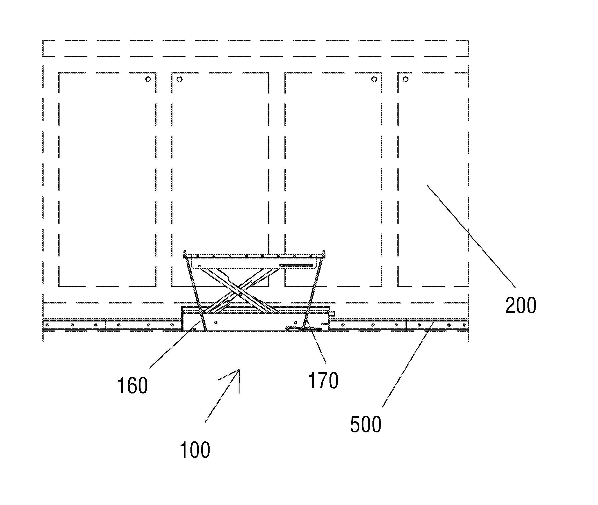
The present invention is a quick folding step stool that can be easily moved and positioned to access various shelves in a cabinet without taking up space. It can be mounted on the existing backing face of the cabinet and requires no modification to the cabinet design. The step stool offers additional benefits such as the option of lighting and motorization. It is also very thin in profile, making it safe for use in areas without an overhang or toe-kick area.

Problems solved by technology

It is also a common issue in commercial facilities with storage rooms, kitchens, filing rooms, computer rooms, and other similar rooms where space is at a premium.
However, in areas where space is at a premium, it can be difficult to store a step stool without interfering with the use of the space, and the stool may be stored in a distant location and be difficult to access.
If the stool is stored in a cabinet or similar storage area, it takes up valuable storage space.
A number of step stools have been designed to hide away by folding or collapsing, but almost all existing solutions require either valuable storage space or require significant modifications to the cabinets or walls.
First, it is fixed to the cabinet and cannot be moved to other locations.
Second, the step, when extended and raised, rises on a vertical support with minimal capability for lateral stabilization other than small flanges on the bottom of the supports.
This makes the step susceptible to overturning.
However, the mechanism disclosed by Kalos requires substantial modification of the cabinets to accommodate the installation of the step.
Furthermore, the step extends well out from the cabinets when deployed, creating an increased hazard of tripping.
However, the step extends well out from the cabinets when deployed, creating an increased hazard of tripping.
Additionally, the Bay device is mounted in a single location on the cabinets and cannot be moved to different locations as needed.
Finally, the Bay device is not suitable for mounting on an unmodified wall, since it requires a large area to retract.
The mechanism disclosed by Hartridge is not collapsible and takes up a substantial amount of storage space in the block of cabinets.
The Hartridge device is therefore not suitable for use along an unmodified wall, since it requires a large amount of space to store.

Method used


Image

  • Compact Folding Step Stool
  • Compact Folding Step Stool
  • Compact Folding Step Stool

Examples


first embodiment

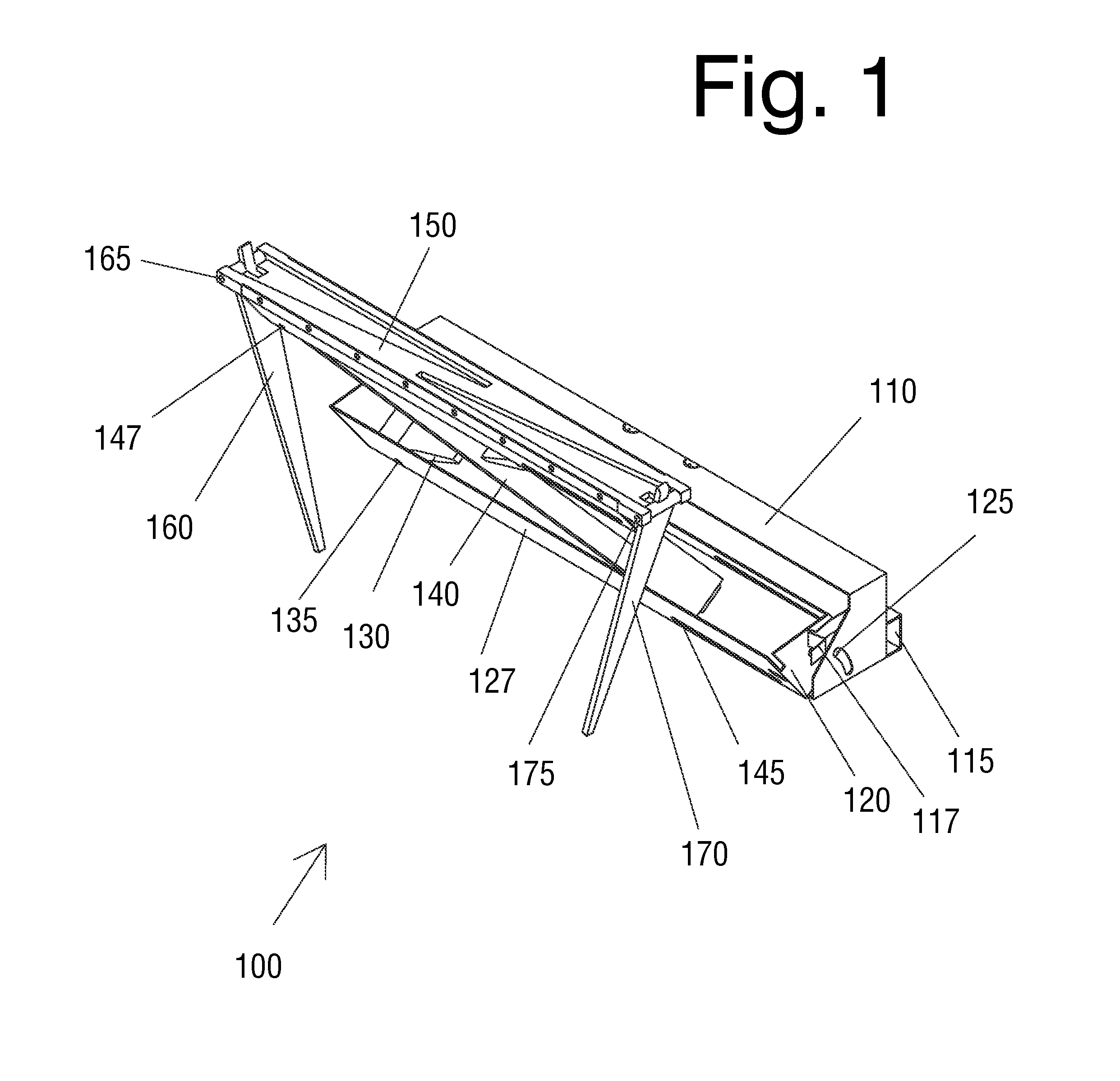
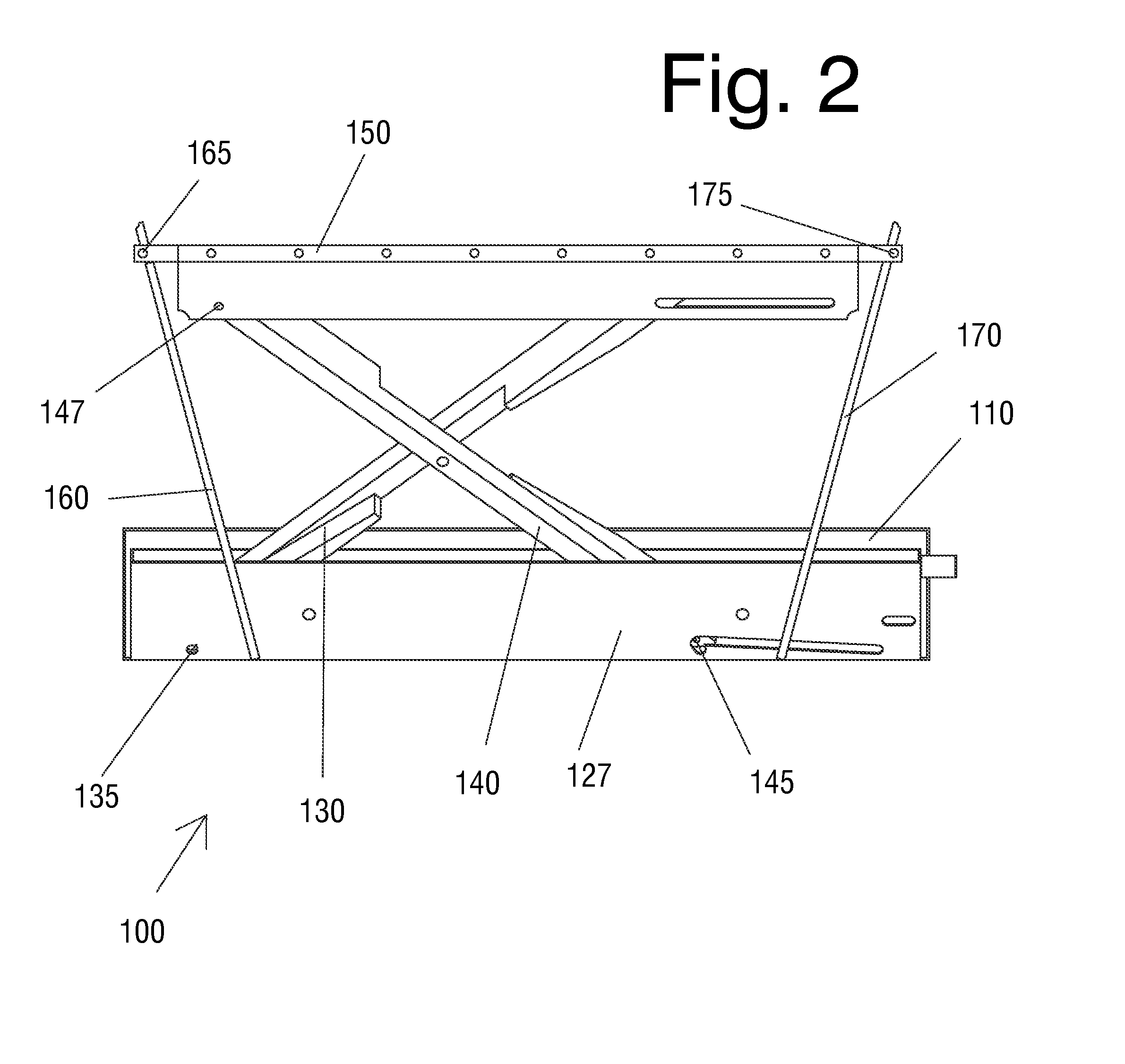
[0034]FIG. 1 depicts an isometric view of the compact quick folding step stool of the present invention. The base of the compact quick folding step stool 100 is a mounting brace housing 110 which houses the extension mechanism, any support stands, step 150, and associated components of the step stool 100 when retracted. An extension mechanism is affixed to, and configured to retract into, the mounting brace housing 110. The extension mechanism includes a rotating housing 120, rear cross member 130, and front cross member 140.

[0035]The rotating housing 120 is connected to the mounting brace housing 110 by a sliding pin 125. The rotating housing 120 can be shaped in a variety of ways, but is preferably configured to present a flat face 127 when rotated into the mounting brace housing 110. In this first embodiment, the rotating housing is maintained in a closed position by a housing catch 117 configured as a flexible piece of metal attached to the mounting brace housing 110 above the s...

fourth embodiment

[0050]FIG. 8 depicts an isometric view of the compact quick folding step stool 100 of the present invention. In this embodiment, the left and right stabilizing stands 160, 170 are replaced by left folding stand 180 and right folding stand 190. Left folding stand 180 is configured to attach to the step 150 with a left upper hinge 183 and to attach to the rotating housing 120 with a left lower hinge 185. The left folding stand is also configured to fold onto itself around left center pivot 187. The right folding stand 190 is similarly configured, being mounted to the step 150 with a right upper hinge 193 and to the rotation housing 120 with a right lower hinge 195. Also like the left folding stand 180, the right folding stand 190 is configured to fold onto itself around a right center pivot 197. The left folding stand 180 and right folding stand 190 are shown here in FIG. 8 extended in a position configured to brace the step 150.

[0051]FIG. 9 illustrates a side view of a fourth embodim...

fifth embodiment

[0054]FIG. 11 depicts an isometric view of the compact quick folding step stool 100 of the present invention. This embodiment uses left folding stand 180 and right folding stand 190 to stabilize the step 150, and also features a light strip 105 mounted to the side of step 150 to provide enhanced visibility when using the step 150. The light strip 105 may be optionally mounted in any location to provide advantageous light. For example, it may be disposed on any side or top of the step 150, on the mounting brace housing 110, on the rotating housing 120, on the cross members, or other similar location. This embodiment also provides a motor 155 mounted to drive a worm gear which can be remotely activated to extend or retract step 150.


PUM


Abstract

A quick folding step stool is provided that folds compactly enough to fit in a cabinet toe-kick area while requiring no modifications to existing cabinets. The quick folding step stool can also be mounted on a track to move laterally along a bank of cabinets. The quick folding step stool or the track can also be mounted on a wall, behind a bar, in a work area, or in any other location where occasional access to higher shelves or other features is required.

Description

FIELD OF THE INVENTION[0001]This invention relates to collapsible steps and, more particularly, to compact collapsible steps which can be mounted on existing walls or cabinets and are movable along the wall or row of cabinets.BACKGROUND OF THE INVENTION[0002]In most buildings, the height of the walls is much greater than the height of the building occupants. When shelves are mounted on a wall, they are typically mounted to likewise extend higher than most can reach. This situation is common in residential kitchens, pantries, closets, and garages. It is also a common issue in commercial facilities with storage rooms, kitchens, filing rooms, computer rooms, and other similar rooms where space is at a premium. The most common solution to this problem is the use of a step stool. However, in areas where space is at a premium, it can be difficult to store a step stool without interfering with the use of the space, and the stool may be stored in a distant location and be difficult to acces...

Claims


Application Information

Patent Timeline
IPC IPC(8): E06C9/06
CPCE06C9/06E06C1/005A47C12/00
Inventor SCHROEDER, JOHN S.
Owner SCHROEDER JOHN S
Learn More