Sheet-transport device, sheet-turning unit and method for turning sheets

Inactive Publication Date: 2013-08-22
EASTMAN KODAK CO
View PDF13 Cites 3 Cited by
  • Summary
  • Abstract
  • Description
  • Claims
  • Application Information

AI Technical Summary

Benefits of technology

[0039]Considering the sheet transport arrangement, preferably at least two of the sheet conveyor devices can be driven by a common driving element. This saves components. In accordance with one embodiment, th

Problems solved by technology

However, this widely used solution has the disadvantage that the turned sheet loses the allocation of the leading edge.
This can result in inaccuracies in the printed image and in view of registration.
One disadvantage of such sheet turning units is that, depending on the properties of the sheet, relative motions between the transport belt and the sheet may occur.
Consequently, positioning inaccuracies may occur after the turning operation.
With a wider configuration of the transport rollers the sheet could be damaged because the

Method used


Image

  • Sheet-transport device, sheet-turning unit and method for turning sheets
  • Sheet-transport device, sheet-turning unit and method for turning sheets
  • Sheet-transport device, sheet-turning unit and method for turning sheets

Examples


Example

[0050]It should be noted that expressions such as above, below, front, back, right and left, as well as similar information, relate to the alignments or arrangements shown in the figures and are only disposed to describe the exemplary embodiments. However, these expressions must not be understood in restricting terms.

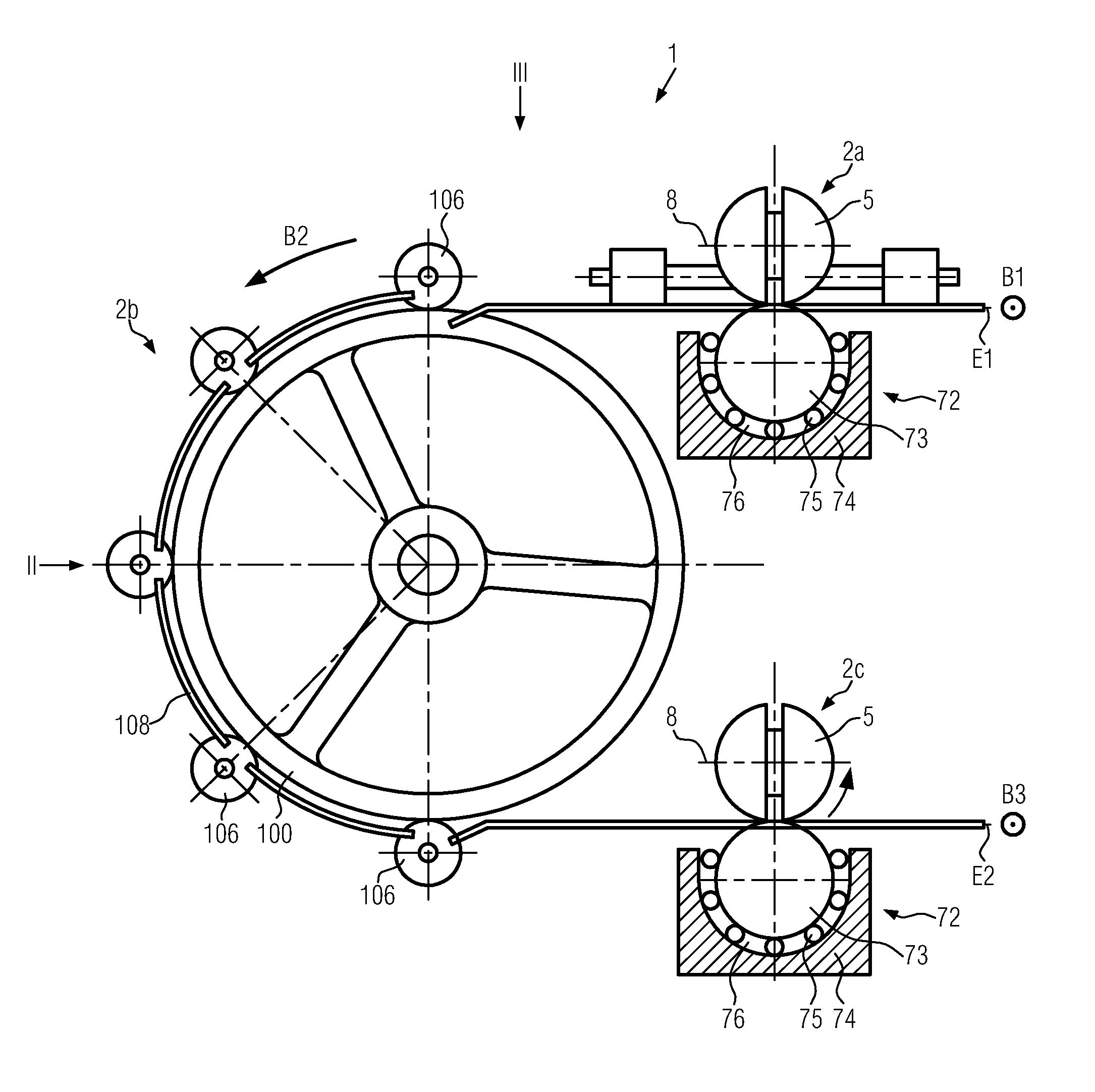
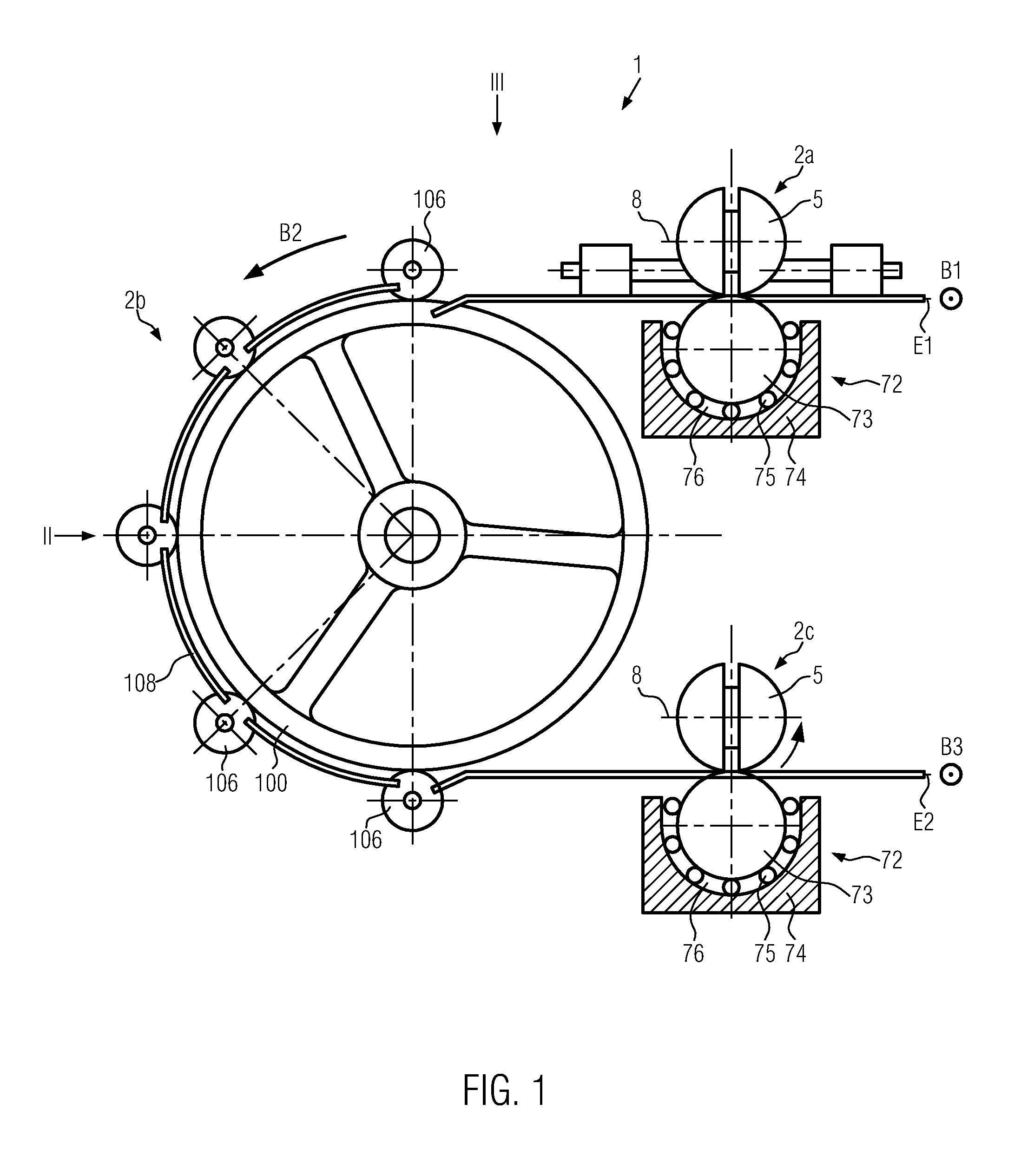
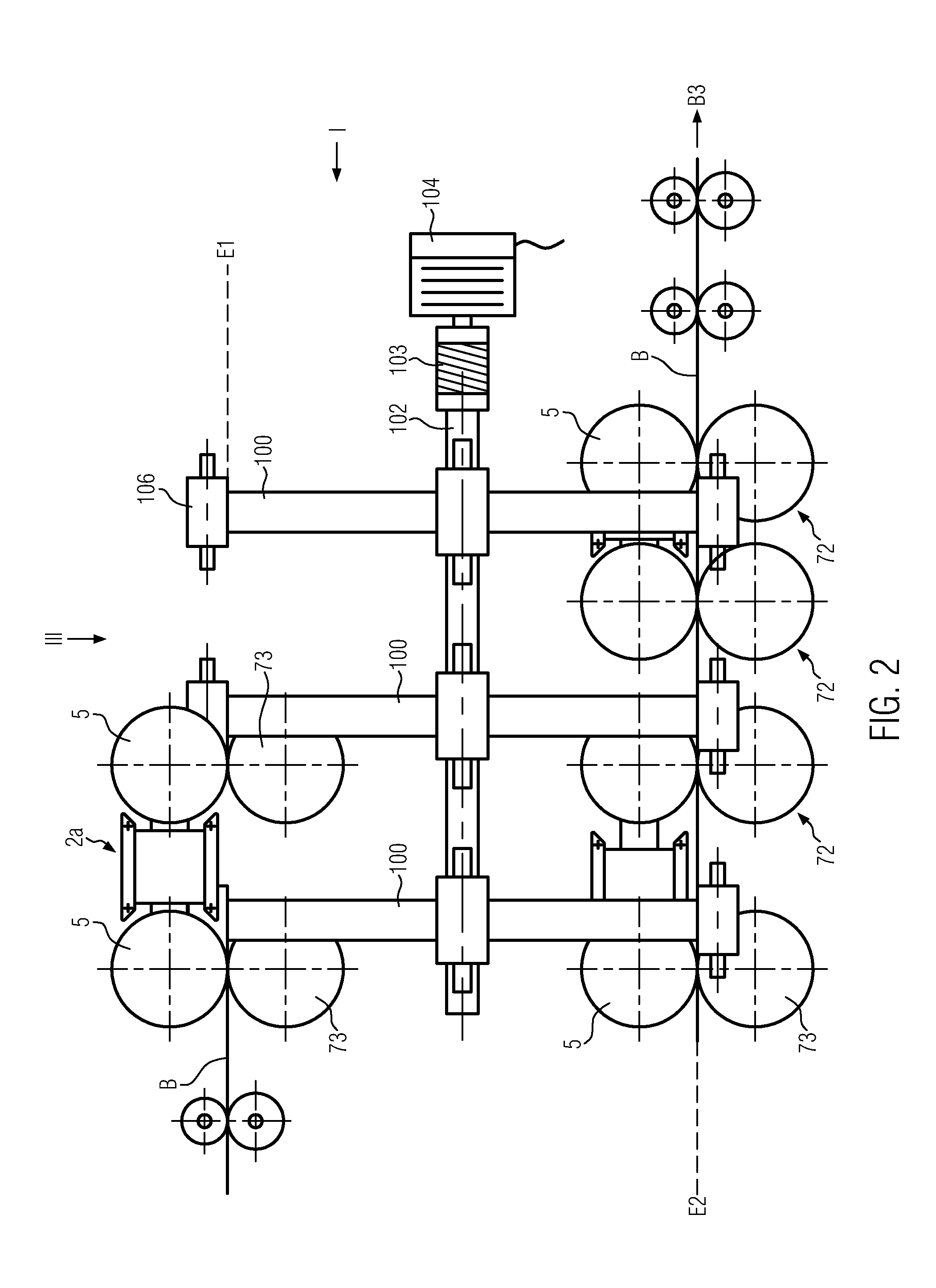
[0051]FIGS. 1, 2 and 3 show various views of a sheet turning unit 1. FIG. 1 is a schematic view of the sheet turning unit 1, viewed from the direction of a first transport path (arrow B1). The transport path B1 extends perpendicularly with respect to the plane of projection of FIG. 1, wherein a sheet B (see FIGS. 2 and 6) is being supplied from a direction below the plane of projection and delivered in a direction toward the upper side of the plane of projection of FIG. 1. FIG. 2 shows a schematic view of the sheet turning unit 1 from the side, i.e., at an angle of 90° relative to the transport path B1. In FIG. 2, the transport path B1 extends from left to right. FIG. 3...


PUM

PropertyMeasurementUnit
Angleaaaaaaaaaa
Angleaaaaaaaaaa
Ratioaaaaaaaaaa

Abstract

Presented herein is a sheet turning unit (1) comprising a first sheet conveyor device (2a) for transporting a sheet at least along a first transport path (B1) in a first plane (E1), and comprising a second sheet conveyor device (2b) for transporting the sheet along a second transport path (B2), said second transport path extending at an angle of 90° with respect to the first transport path (B1) and, in sum, describing a curve of 180°, whereby the starting point of said curve is located in the first plane (E1) and the end point of said curve is located in a second plane (E2) that is different from the first plane, and comprising a third sheet conveyor device (2c) for transporting the sheet along at least a third transport path (B3). As a result of this, the leading edge of the sheet remains in front even after the turning operation, and a precisely functioning and reliable sheet turning unit is being provided. Furthermore, advantageous embodiments of the first and third sheet conveyor devices are described, said devices enabling the transport of a sheet in two directions. The advantageous embodiments of the first and third sheet conveyor devices are compact and simple in design and can be controlled easily. The advantageous embodiments of the first and third sheet conveyor devices comprise a sheet transport body that, by means of a rotating mechanism arranged in the sheet transport body, can be rotated about a first rotational axis and a second rotational axis, said axes extending through one point of intersection and being perpendicular to one another.

Description

TECHNICAL FIELD OF THE INVENTION[0001]The present invention relates to a sheet transporting and turning unit for transporting and / or turning sheets in printing machines of other processing machines, as well as to a method for turning sheets. Furthermore, the present invention relates to sheet conveyor devices for transporting sheets in printing machines or the processing machines, and, in particular, to sheet conveyor devices that are suitable for transporting a sheet in two directions.BACKGROUND ART[0002]In the course of the processing, in particular the printing, of sheets it is frequently necessary to turn the sheet so that it be processed on both sides. For example, in known printing machines, a sheet turning device is provided, said device turning a sheet with the use of turning pockets. In such a sheet turning device comprising turning pockets, a sheet is first supplied in one direction by means of transport rollers and then fed into a sheet guide that is configured as a turni...

Claims


Application Information

Patent Timeline
IPC IPC(8): B65H15/00
CPCB65H5/062B65H15/00B65H2301/33214B65H2301/33224B65H2301/3423B65H2403/43B65H2801/21B65H2404/141B65H2404/144B65H2404/696B65H2404/6961B65H2801/15B65H2403/483
Inventor DOBRINDT, DIRK
Owner EASTMAN KODAK CO
Why Eureka
Try Eureka