Inkjet printer and correction value acquisition method

a correction value and printer technology, applied in printing, other printing apparatus, etc., can solve the problems of inability to acquire density correction values for outlets, inability to acquire density correction values, and inability to achieve appropriate density correction values for outlets

Active Publication Date: 2013-08-22
DAINIPPON SCREEN MTG CO LTD
View PDF2 Cites 9 Cited by
  • Summary
  • Abstract
  • Description
  • Claims
  • Application Information

AI Technical Summary

Benefits of technology

[0004]The present invention is intended for an inkjet printer, and it is an object of the present invention to acquire appropriate density correction values of a plurality of outlets in a short time even if an ink ejection failure occurs in any of the outlets.
[0006]According to the present invention, appropriate density correction values of the plurality of outlets can be acquired in a short time even if an ink ejection failure occurs in any of the outlets.
[0007]In a preferable mode of the present invention, a check pattern having linear portions formed with ink ejected from respective outlets is printed together with the pattern for density correction on the base material, the image data indicating the pattern for density correction and the check pattern on the base material is acquired, and the target outlet detection part detects the target outlet based on an extent to which each linear portion is missing in the check pattern. This enables accurate detection of the target outlet.

Problems solved by technology

Incidentally, with inkjet printers, ink ejection failures (also called “failing nozzles” or “missing dots”) may arise due to clogged outlets caused by ink hardening or adherence of debris such as paper dust or due to the effect of air bubbles in the ink inside the head.
If an ink ejection failure occurs in any of a plurality of outlets when (at the time of or during) printing a pattern for density correction on printing paper, appropriate density correction values for the outlets cannot be acquired.
In this case, it is necessary to perform cleaning processing and then re-print the pattern for density correction, thus taking a long time to acquire density correction values.

Method used


Image

  • Inkjet printer and correction value acquisition method
  • Inkjet printer and correction value acquisition method
  • Inkjet printer and correction value acquisition method

Examples


Embodiment Construction

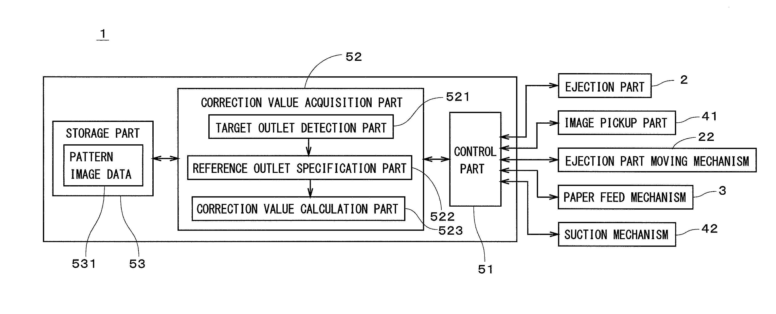
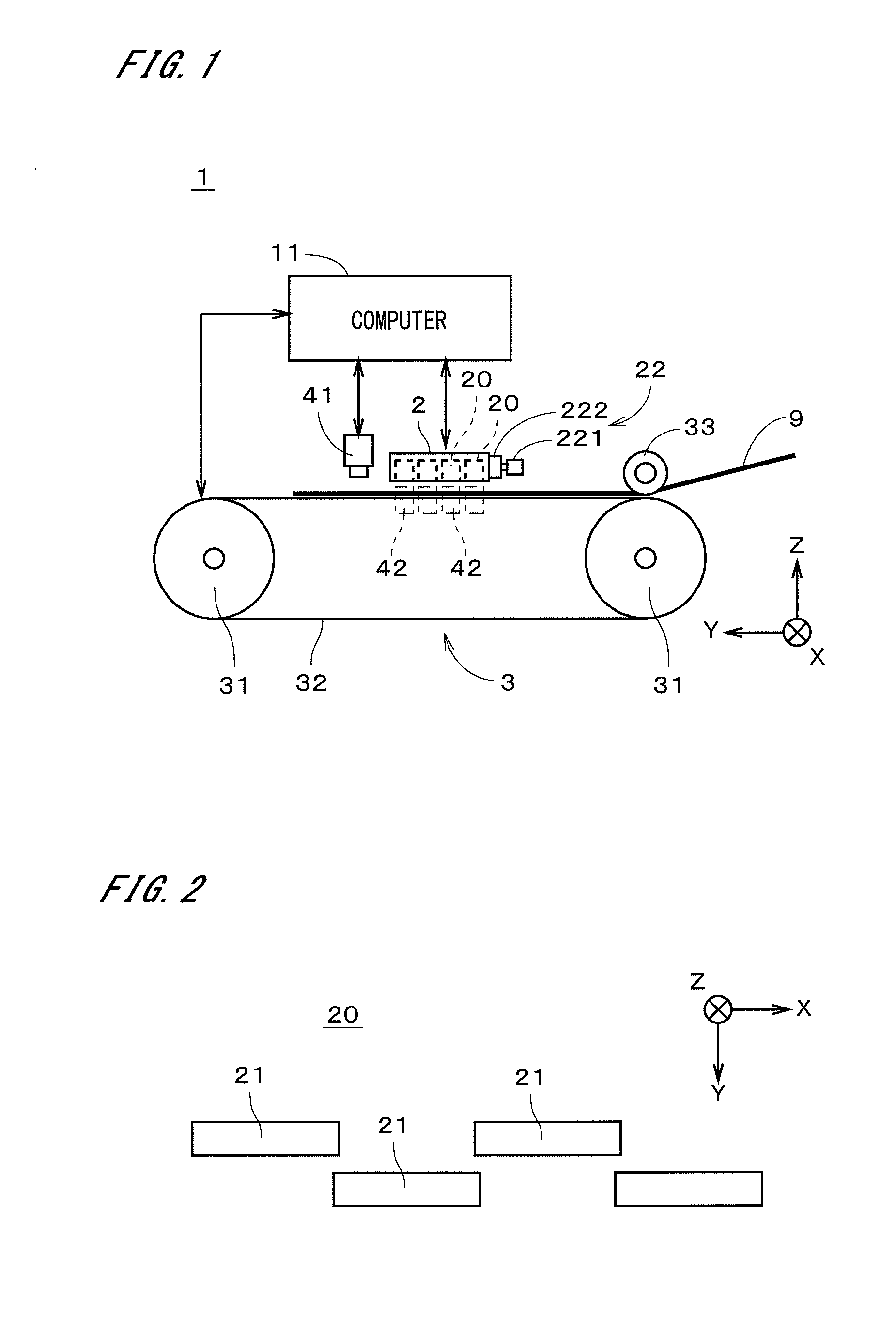
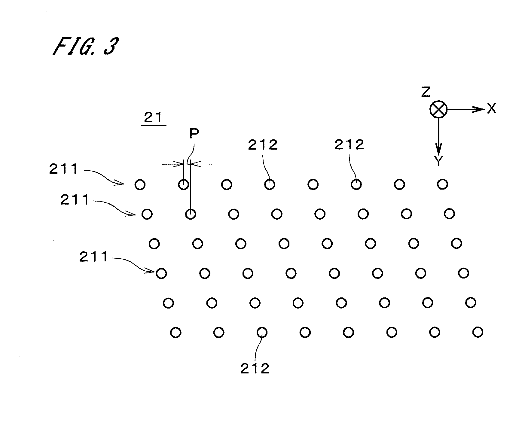
[0022]FIG. 1 shows a configuration of an inkjet printer 1 according to an embodiment of the present invention. The inkjet printer 1 is an image recording apparatus that records images of a plurality of color components on printing paper 9 that is continuous paper so as to superimpose the images. The inkjet printer 1 includes an ejection part 2 that ejects fine droplets of ink toward the printing paper 9, an ejection part moving mechanism 22 for moving the ejection part 2 in the X direction in FIG. 1, a paper feed mechanism 3 for moving the printing paper 9 in the Y direction perpendicular to the X direction under the ejection part 2, an image pickup part 41 that is disposed close to the (+Y) side of the ejection part 2, and a computer 11 that is connected to the ejection part 2, the ejection part moving mechanism 22, the paper feed mechanism 3, and the image pickup part 41. Hereinafter, the direction of movement of the printing paper 9 (i.e., Y direction) is referred to as a “scanni...


PUM


Abstract

In an inkjet printer, a pattern for density correction that indicates a constant density image is printed on printing paper with a head having a plurality of outlet rows, and pattern image data that indicates the pattern is acquired. A target outlet that ejects ink toward a linear region having a missing part in the pattern is detected, and a reference outlet that is included in the same outlet row as the target outlet and located close to the target outlet is specified. A density correction value of the target outlet among density correction values that are acquired based on a density profile of the pattern is replaced with a representative value of a density correction value of the reference outlet. Through this, even if an ink ejection failure occurs in any of the outlets, appropriate density correction values can be obtained for a plurality of outlets.

Description

TECHNICAL FIELD[0001]The present invention relates to an inkjet printer and a correction value acquisition method.BACKGROUND ART[0002]Conventionally, inkjet printers that print an image by ejecting fine droplets of ink from a plurality of outlets of a head toward printing paper while moving the printing paper relative to the head have been used. Also, a pattern for density correction that indicates a constant density image has been printed on printing paper with a plurality of outlets and the distribution of densities in the image on the printing paper has been measured so as to acquire a plurality of density correction values of the outlets and achieve uniform print densities of the outlets using the density correction values (so-called shading compensation). For example, Japanese Patent Application Laid-Open No. 6-166247 discloses a method in which, in addition to a pattern A for use in detecting unevenness of the recording density of a recording head, a pattern B that is printed ...

Claims


Application Information

Patent Timeline
Patent Type & Authority Applications(United States)
IPC IPC(8): B41J2/12
CPCB41J2/2146B41J2/12
Inventor HATANO, KEIJI
Owner DAINIPPON SCREEN MTG CO LTD
Why Eureka
Try Eureka