
Position-adjustable gas regulator

a gas regulator and position adjustment technology, applied in the direction of fluid pressure control, process and machine control, instruments, etc., can solve the problems of affecting the user's ability to effectively read the pressure gauge, the user is not able to radially vary the position of the dual burst disk, and the pressure gauge, etc., to achieve negligible weight, and the effect of quick and effective means of adjusting

Inactive Publication Date: 2013-08-29
PRESSURE SPECIALIST
View PDF16 Cites 3 Cited by
  • Summary
  • Abstract
  • Description
  • Claims
  • Application Information

AI Technical Summary

Benefits of technology

The present regulator has a collar that allows for easy adjustment of the position of the regulator's projections without compromising its safety. This collar is lightweight and highly accurate, and it allows for quick and effective adjustments. The technical effect of the invention is the added ability to quickly and safely adjust the location of the regulator's projections.

Problems solved by technology

In this fully engaged position, the user is not able to radially vary the position of the dual burst disks, pressure gauge, and fill nipple.
In these immoveable positions the profiles of the components interfere or impinge upon the user's wrist and arm and also interfere with the user's ability to effectively read the pressure gauge.

Method used


Image

  • Position-adjustable gas regulator
  • Position-adjustable gas regulator
  • Position-adjustable gas regulator

Examples


Embodiment Construction

[0023]While the present invention is susceptible of embodiment in various forms, there is shown in the drawings and will hereinafter be described a presently preferred embodiment with the understanding that the present disclosure is to be considered an exemplification of the invention and is not intended to limit the invention to the specific embodiment illustrated.

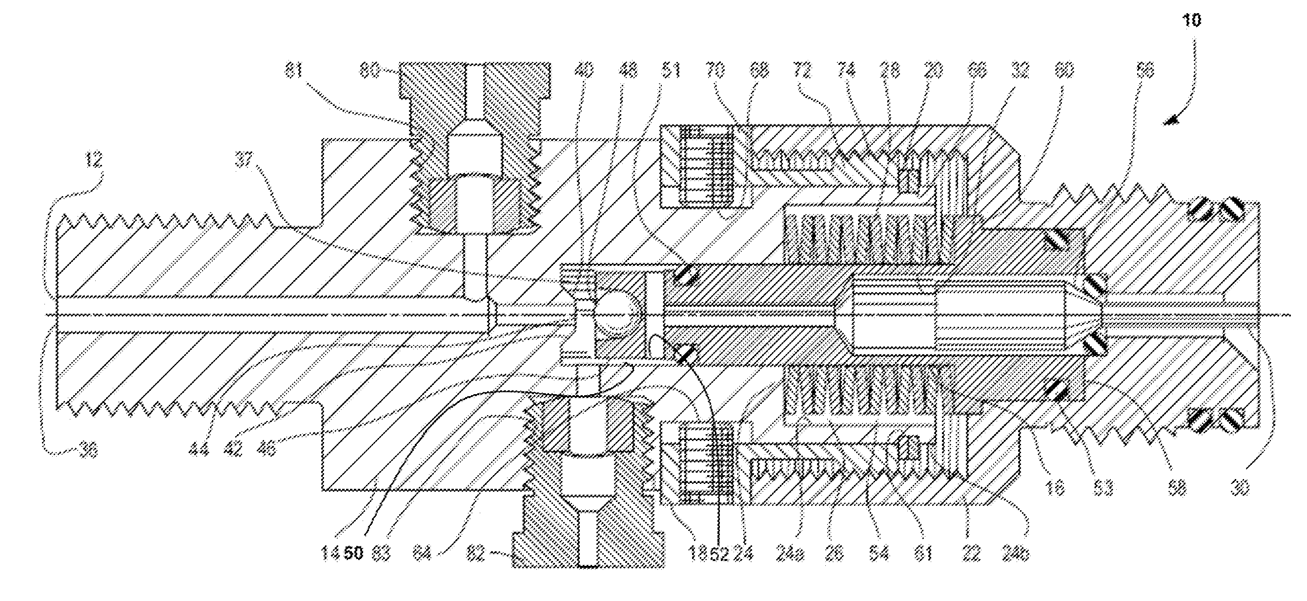
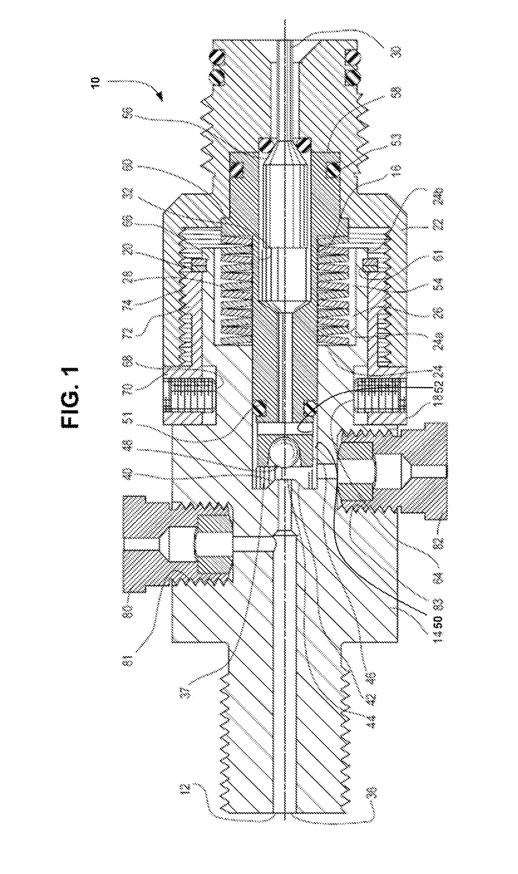
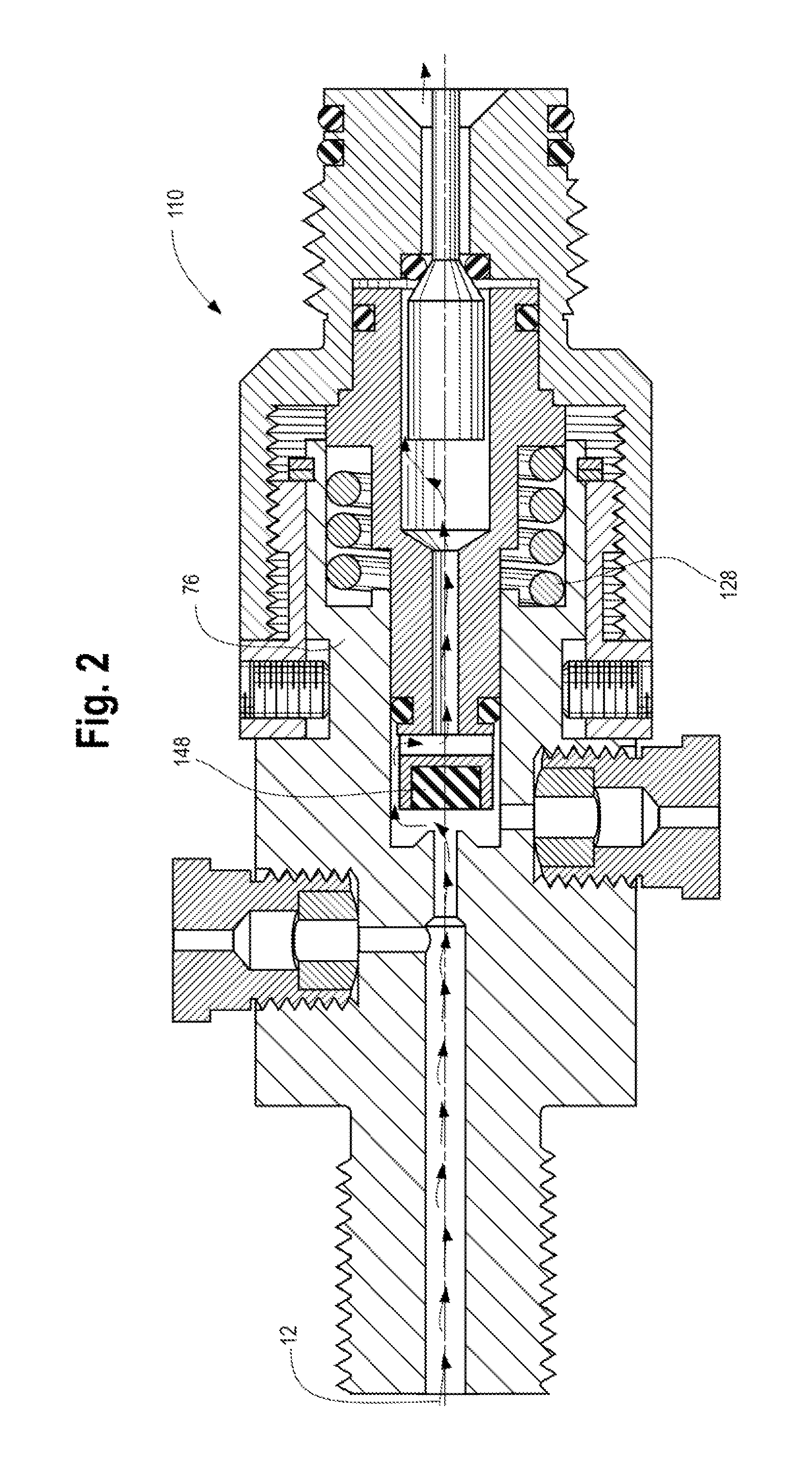
[0024]Referring to the figures and briefly to FIG. 1, a present regulator 10 is shown in the open condition such that a regulated flow path, indicated generally at 12, is provided from a high pressure gas source to a downstream device such as a paint ball gun or the like. The controlled downstream pressure is regulated essentially regardless of the higher upstream pressure. An exemplary regulator is disclosed in Carroll, U.S. Pat. No. 6,851,447, which is commonly assigned with the present application, and the disclosure of which is incorporated herein by reference.

[0025]The regulator 10 includes generally, a main body 14,...


PUM


Abstract

A pressure regulator for controlling the flow of gas from a high pressure source to a low pressure device includes a body having a high pressure inlet defining a seat. An adjusting collar has a centrally located bore. The collar engages the body at any predefined radial orientation. The collar has a thread and is securable to the body at the selected radial orientation. The regulator also has a threaded bonnet to engage the collar. A locking ring engages the body and secures the adjusting collar to the body. A piston has a central bore and is disposed within a piston chamber that defines a gap between the piston and a wall. The piston is movable between an open condition and a closed condition. A spring moves the piston to the open condition. A pin valve is disposed in the central longitudinal bore in the piston.

Description

CROSS-REFERENCE TO RELATED APPLICATION DATA[0001]This application claims the benefit of priority of Provisional U.S. Patent Application Ser. No. 61 / 603,757, filed Feb. 27, 2012, the disclosure of which is incorporated herein by reference in its entirety.BACKGROUND OF THE INVENTION[0002]The present invention is directed to a novel adjustable locking collar for use on a pressure regulator. More particularly, the present invention relates to an adjustable locking collar that engages both the main body and the bonnet of a pressure regulator for use in paint ball guns that use compressed gas to fire projectiles. The present invention is also adapted for use with other pressurized gas devices.[0003]Sporting events that provide the participant with an adventure in military strategy and the feel of the fear and exhilaration of battle have become very popular. Generally participants are equipped with a gas projectile gun or rifle and protective gear, and are divided into two or more combat g...

Claims


Application Information

Patent Timeline
Patent Type & Authority Applications(United States)
IPC IPC(8): F16K31/36
CPCG05D16/103G05D16/00Y10T137/7793
Inventor SCHREIBER, JEFF
Owner PRESSURE SPECIALIST
Learn More