Image processing device, image processing method, and program

a technology of image processing and image capturing, applied in the field of display, can solve the problems of difficult to grasp the correspondence relationship between both, and the arrangement of captured images to be displayed is not compatible with the arrangement of image capturing, so as to facilitate grasping and managing the contents

Active Publication Date: 2013-08-29
CANON KK
View PDF2 Cites 77 Cited by
  • Summary
  • Abstract
  • Description
  • Claims
  • Application Information

AI Technical Summary

Benefits of technology

[0008]According to the present invention, it is made possible to intuitively grasp the correspondence relationship between a captured image and an image captu

Problems solved by technology

Consequently, in the case where images are captured with the camera array held horizontally, in which rotation of the image is not necessary, no problem occurs, but, in the case where images are captured with the camera array held vertically, there arises such a problem that the arrangement of captured images to be displayed does not agree with the arrangement of the image capturing un

Method used


Image

  • Image processing device, image processing method, and program
  • Image processing device, image processing method, and program
  • Image processing device, image processing method, and program

Examples


first embodiment

[0031]Hereinafter, preferred embodiments of the present invention are explained in detail. Configurations shown in the following embodiments are only examples and the present invention is not limited to the configurations shown schematically.

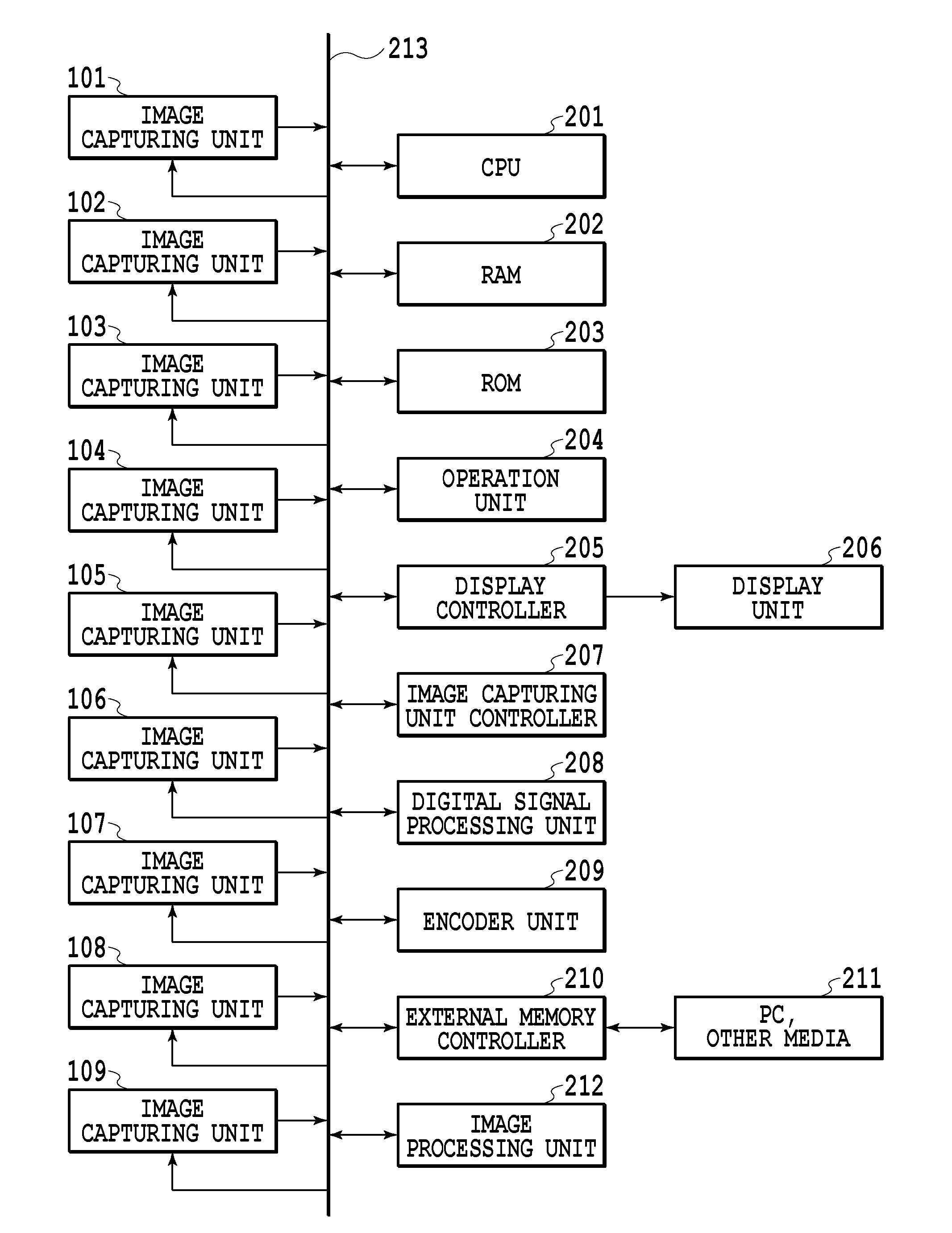
[0032]FIG. 1 is a diagram showing an external appearance of the front of a camera array image capturing device (camera array) according to a first embodiment. In FIG. 1, a body of a camera array 100 includes nine image capturing units 101 to 109 that acquire an image and an image capturing button 110. In the case that the image capturing button 110 is pressed down, the image capturing units 101 to 109 receive light information of a subject with a sensor (image capturing element) and the received signal is A / D-converted and captured image data (digital data) including a plurality of captured images is acquired at the same time. By such a camera array, it is possible to obtain a group of captured images in which the same subject is captured from a...

second embodiment

[0067]In the first embodiment, the case is explained where the captured image data including nine image files obtained by one-time image capturing is displayed. Next, a case is explained as a second embodiment where captured image data obtained by multiple-time image capturing is displayed, in which captured image data captured by a general digital camera having a single image capturing unit is included mixedly. Explanation of parts common to those of the first embodiment is simplified or omitted and here, different points are explained mainly.

[0068]FIG. 12 shows an example of a data structure of captured image data in the present embodiment. Captured image data denoted by reference numerals 1201, 1202, 1205, and 1206 is data including one image file the images of which are captured by a digital camera having a single image capturing unit. Captured image data denoted by reference numerals 1203 and 1204 is data including nine image files the images of which are captured simultaneousl...

third embodiment

[0075]Next, an aspect is explained as a third embodiment, in which only captured images selected by a user are displayed among a plurality of captured images obtained by a camera array. Explanation of parts common to those of the first and second embodiments is simplified or omitted and here, different points are explained mainly.

[0076]FIG. 14 is a diagram showing an external appearance of a camera array used in the present embodiment. In FIG. 14, the body of a camera array 1400 includes 25 image capturing units 1401 to 1425 that capture images and an image capturing button 1430. The internal configuration is the same as that of the camera array 100 in the first embodiment except in that the number of image capturing units is different and the flow of processing in the image processing unit 212 is also substantially the same. The present embodiment is characterized by the image output processing at step 403 in the flowchart of FIG. 4, and therefore, hereinafter, the contents of the ...


PUM


Abstract

In a case of a camera array, the arrangement of image capturing units and the arrangement of captured images that are displayed do not agree with each other depending on the orientation of the camera at the time of image capturing and it is hard to grasp the correspondence relationship between both. An image processing device for processing a plurality of images represented by captured image data obtained by a camera array image capturing device including a plurality of image capturing units includes a determining unit configured to determine, on the basis of a display angle of the images in a display region, an arrangement of each image in the display region corresponding to each of the plurality of image capturing units, and the arrangement of each image in the display region is determined based on the arrangement of the plurality of image capturing units.

Description

BACKGROUND OF THE INVENTION[0001]1. Field of the Invention[0002]The present invention relates to a display method for displaying an image obtained by using a camera array image capturing device (also referred to simply as a “camera array”, as known as camera array system, multiple lens camera, and the like) including a plurality of image capturing units.[0003]2. Description of the Related Art[0004]Conventionally, as a technique to display a plurality of captured images obtained at one time by a camera array image capturing device (hereinafter, referred to as a camera array) including a plurality of image capturing units, a list display technique to display two captured images arranged horizontally side by side is known (for example, Japanese Patent Laid-Open No. H11-088912 (1999)). By simultaneously outputting two captured images with a parallax captured by two image capturing units on the display by arranging them side by side in the horizontal direction, the list display technique...

Claims


Application Information

Patent Timeline
IPC IPC(8): H04N5/232
CPCH04N5/247H04N5/23293H04N5/268H04N23/631H04N23/90
Inventor KANEKO, CHIAKI
Owner CANON KK
Why Eureka
Try Eureka