
Object finder mounting apparatus, systems for viewing objects and methods for using same

Active Publication Date: 2013-08-29
NANTONG SCHMIDT OPTO ELECTRICAL TECH CO LTD
View PDF3 Cites 4 Cited by
  • Summary
  • Abstract
  • Description
  • Claims
  • Application Information

AI Technical Summary

Benefits of technology

The invention is an object-finder-mounting apparatus for optical instruments that allows for easy mounting and use of an object finder. The apparatus includes a base, an object-finder holder, a shadow-casting member, and a projection plate. The apparatus can be used in two different modes: a first mode where the object finder is held and a second mode where the object finder is removed and the projection plate is moved to a position where it can cast a shadow. The apparatus can be adjusted to align the object finder with the optical instrument and can be used with various optical instruments such as spotting scopes, red beam finders, and laser pointers. The technical effects of the invention include improved ease of use and versatility in mounting and using an object finder with optical instruments.

Problems solved by technology

Because this user-input information may have errors and / or because of other inaccuracies, auto-tracking telescope systems may exhibit tracking errors (where the target celestial object moves away from the center of the field of view of the telescope), particularly over extended periods of observation.
For example, an existing spotting scope designed to find distant stars cannot be used to observe the sun without the potential for causing damage to the eye of the observer.

Method used


Image

  • Object finder mounting apparatus, systems for viewing objects and methods for using same
  • Object finder mounting apparatus, systems for viewing objects and methods for using same
  • Object finder mounting apparatus, systems for viewing objects and methods for using same

Examples


Embodiment Construction

[0042]Throughout the following description, specific details are set forth in order to provide a more thorough understanding of the invention. However, the invention may be practiced without these particulars. In other instances, well known elements have not been shown or described in detail to avoid unnecessarily obscuring the invention. Accordingly, the specification and drawings are to be regarded in an illustrative, rather than a restrictive, sense.

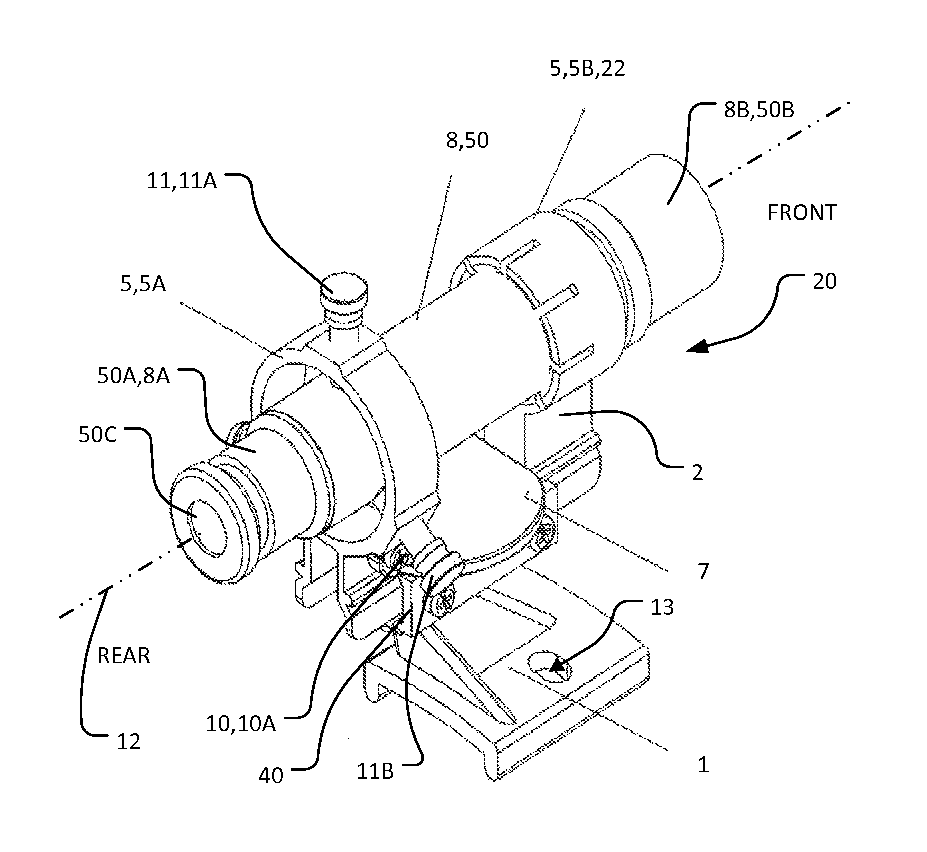
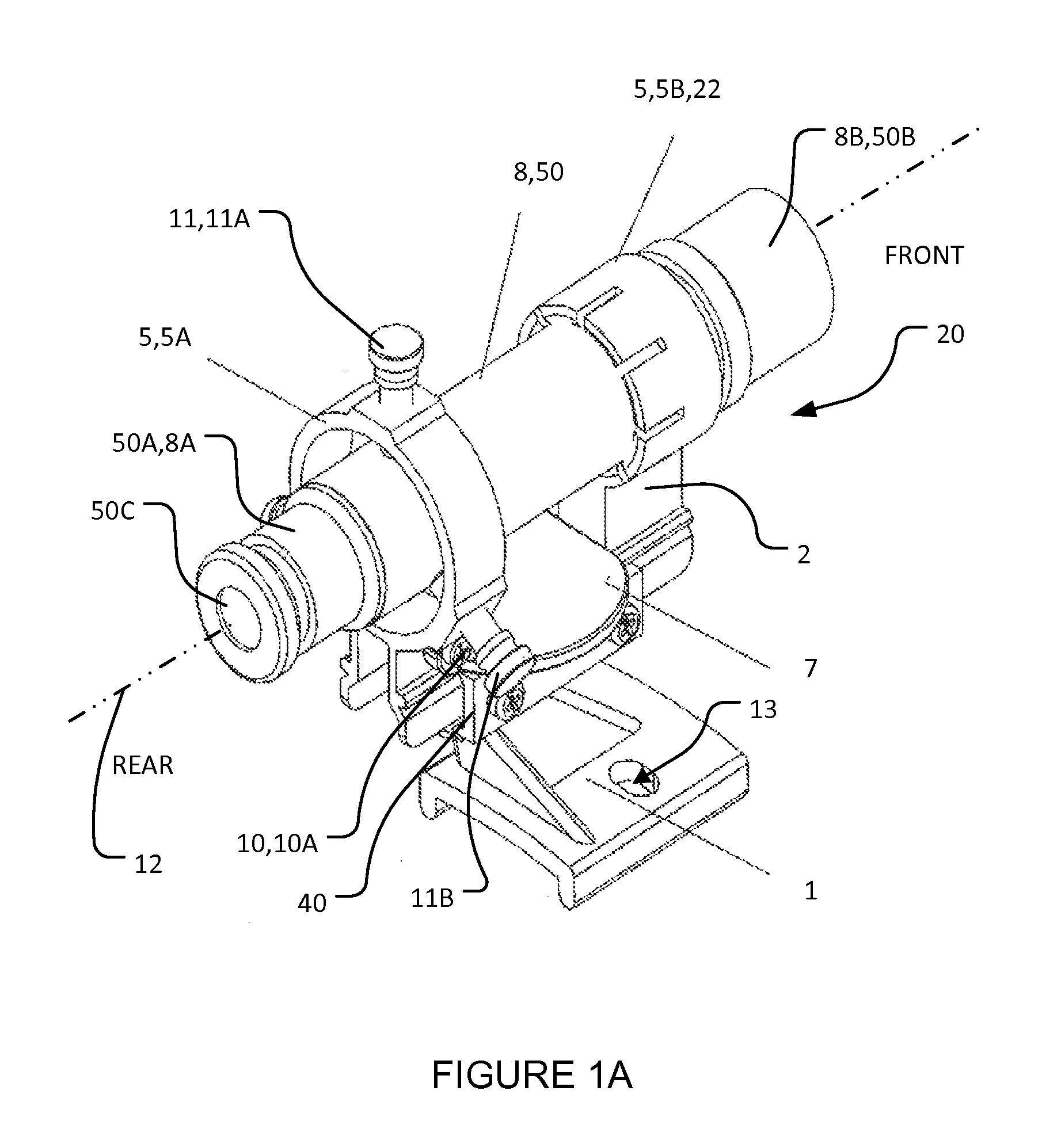
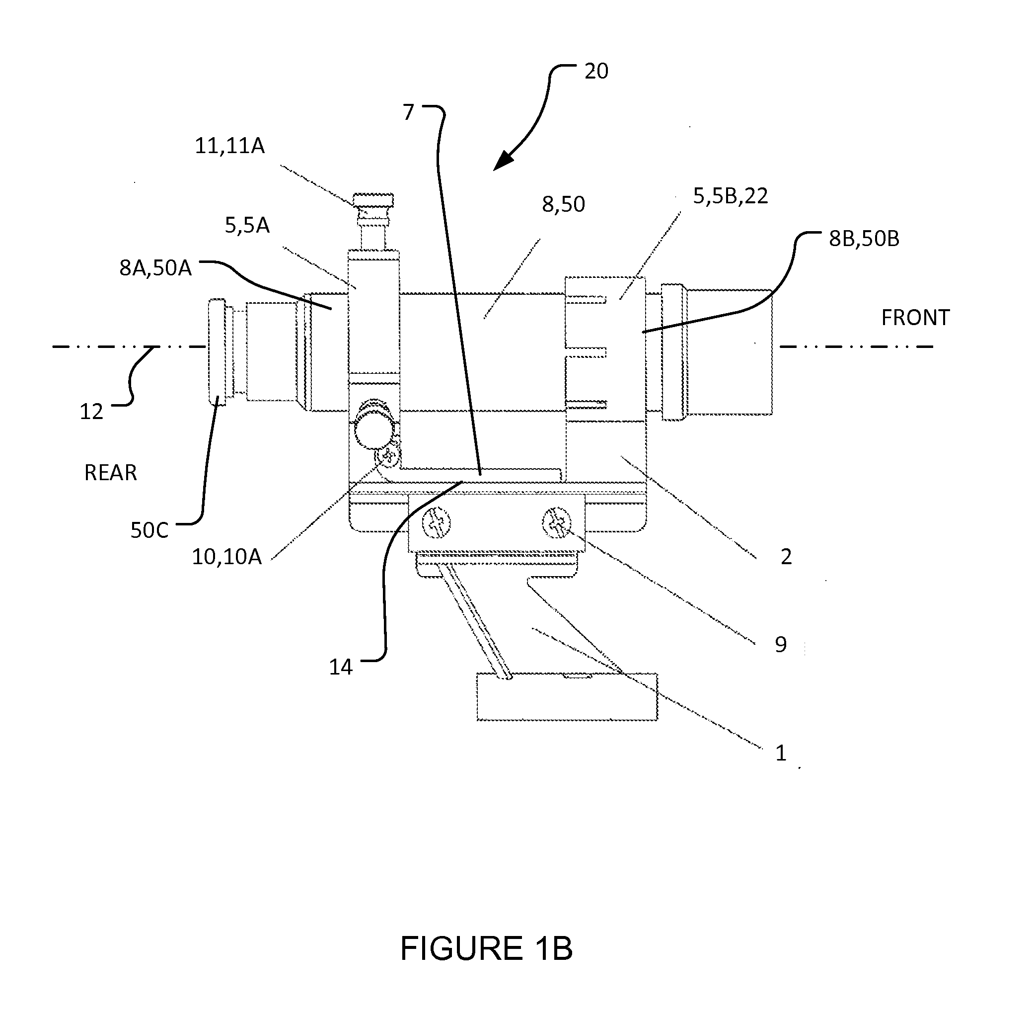
[0043]FIGS. 1A-1E (collectively, FIG. 1) show an object-finder-mounting apparatus 20 according to an example embodiment of the invention in a first working mode. FIGS. 2A-2E (collectively, FIG. 2) show object-finder-mounting apparatus 20 in a second working mode. Object-finder-mounting apparatus 20 of the illustrated embodiment (FIGS. 1 and 2) comprises: a base 1 which is couplable to a primary optical instrument 30 (FIG. 1E, FIG. 2E); an object-finder-holder assembly 2 which extends from base 1 and which provides one or more object-f...


PUM


Abstract

An object-finder-mounting apparatus comprises: a base for mounting the object-finder-mounting apparatus to an optical instrument; an object-finder-holder assembly coupled to the base and comprising one or more object-finder holders for removably holding an object finder; a projection plate moveably coupled to the base and / or the object-finder-holder assembly for movement between first and second positions; and a shadow-casting member. The object-finder-mounting apparatus is convertible between first and second working modes. In the first working mode, the projection plate is moved to the first position which permits use of the object finder held by the object-finder holders to locate objects. In the second working mode, the object finder is removed from the object-finder holders and the projection plate is moved to the second position. In the second working mode, the shadow-casting member casts a shadow onto the projection plate when the optical instrument is directed toward a luminous object.

Description

RELATED APPLICATIONS[0001]This application is a continuation in part of Patent Cooperation Treaty application No. PCT / CN2012 / 000265 filed 2 Mar. 2012 which in turn claims priority from Chinese patent application No. CN201210048219 filed 29 Feb. 2012, both of which are hereby incorporated herein by reference.TECHNICAL FIELD[0002]The present invention relates to optical instruments. Particular embodiments provide object-finder-mounting apparatus which may mount object finders (e.g. spotting scopes and the like) to primary optical instruments, such as telescopes, surveying instruments and / or the like.BACKGROUND[0003]So-called spotting scopes (also known as finderscopes) are examples of object finders which may be used in conjunction with primary (typically high-magnification) optical instruments. By way of non-limiting example, such primary optical instruments may include telescopes (e.g. in the field of astronomy), surveying instruments and / or the like. Spotting scopes function as obj...

Claims


Application Information

Patent Timeline
IPC IPC(8): G02B23/14
CPCG02B23/16G02B23/14
Inventor SHEN, DAR-TSON
Owner NANTONG SCHMIDT OPTO ELECTRICAL TECH CO LTD
Learn More