Cooling Structure for Cooling Electric Motor for Vehicle

Inactive Publication Date: 2013-09-05
KAWASAKI HEAVY IND LTD
View PDF8 Cites 30 Cited by
  • Summary
  • Abstract
  • Description
  • Claims
  • Application Information

AI Technical Summary

Benefits of technology

[0029]According to the cooling structure for cooling the electric motor for a vehicle according to the present invention, by including the means to feed the coolant, the coolant is made to be ejected from the ejection hole to the coil end of the stator at a suitable ejection pressure. Accordingly, although the cooling structure has a simplified structure, a suitable amount of the coolant can be directly sprayed onto the coil end which ea

Problems solved by technology

A leading cause of the heat is generation of heat (so-called copper loss) from a coil attributable to resistance of an electrical current flowing through windings.
This increases temperature of the coil, resulting in an increase in the electrical resistance of the windings and a

Method used


Image

  • Cooling Structure for Cooling Electric Motor for Vehicle
  • Cooling Structure for Cooling Electric Motor for Vehicle
  • Cooling Structure for Cooling Electric Motor for Vehicle

Examples


first embodiment

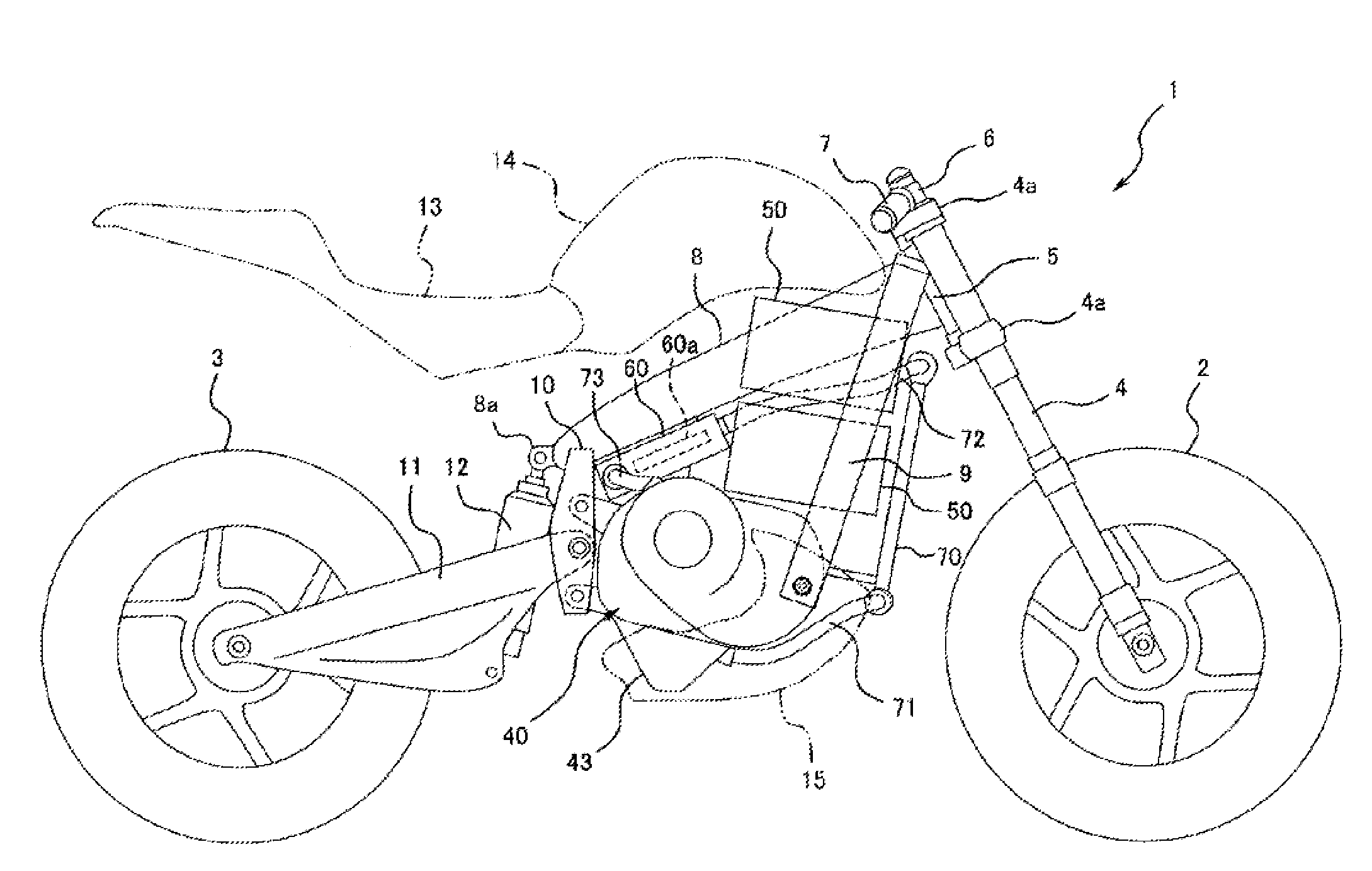
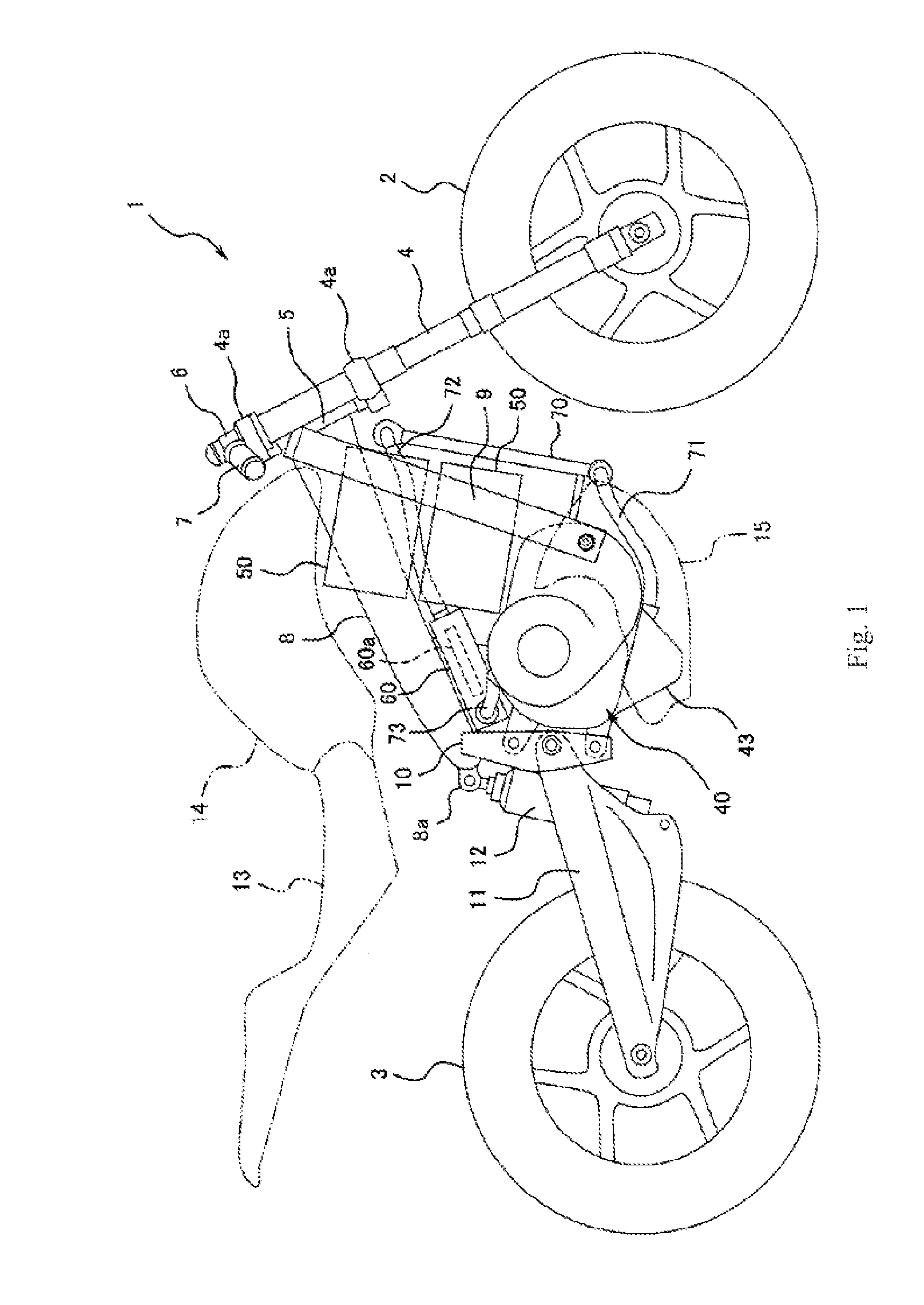
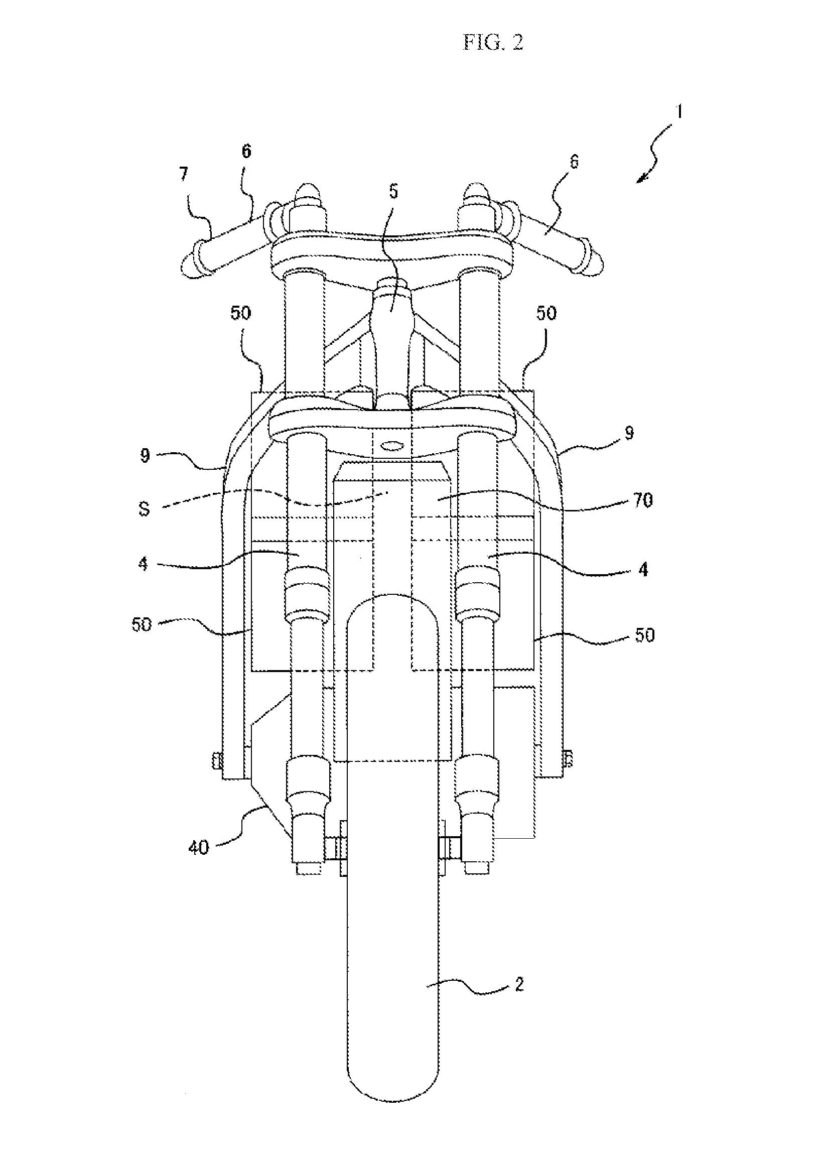
[0041]FIG. 1 is a right side view illustrating the main parts, such as a body frame, a power plant, and wheels, of an electric motorcycle 1 (electric vehicle) according to a first embodiment of the present invention, and FIG. 2 is a front view illustrating the same viewed from the front. As illustrated in FIG. 1, the electric motorcycle 1 includes a front wheel 2 as a steering wheel and a rear wheel 3 as a driving wheel. The front wheel 2 is freely rotatably supported by lower ends of a pair of left and right front forks 4 which almost vertically extend. On the one hand, upper portions of the front forks 4 are supported by a steering shaft (not illustrated) via upper and lower brackets 4a.

[0042]The steering shaft is freely rotatably supported in a state of being inserted in a head pipe 5 of the body, and constitutes a steering shaft. That is, a handle 6, which horizontally extends like a bar, is attached to the upper bracket 4a, and the driver can achieve steering by swinging the f...

second embodiment

[0079]FIGS. 6 and 7 illustrate an electric motorcycle 101 according to a second embodiment of the present invention. Both figures are equivalent to FIGS. 1 and 3 according to the first embodiment, respectively. Although an electric motorcycle 101 of the second embodiment mainly differs in the structure of a power plant from the first embodiment and hence differs also in the mounting positions of batteries 50 and a power control controller 60, there are no other differences in the other basic structure. Accordingly, equivalent members are denoted by identical reference signs and a description thereof is omitted.

[0080]A power plant 80 of the second embodiment does not include a transmission device 30 so that the power plant 80 is very compact in a forward and rearward direction as illustrated in FIG. 6. For this reason, as illustrated in the drawing, down frames 9 extend rearward from a lower end, and a case member of the power plant 80 is fastened to a rear end. In addition, a pivot ...


PUM


Abstract

In an electric motor for a vehicle (21) which includes a stator (21) fixed to an outer case member (41) side, and a rotor (22) which rotates relative to the stator (21), an ejection hole (45b) for ejecting a coolant is provided in a disc-like member (45) which faces an end face in a rotary shaft direction of the rotor (22), non-conducting oil for cooling is fed from an oil pump (46) to a fluid path (41c) communicating with the ejection hole (45b), and the oil ejected from the ejection hole (45b) is sprayed onto at least a coil end (21a) of the stator (21). With this configuration, it is possible to provide a cooling structure for cooling a motor which, even though having a simple structure, can stably and efficiently cool the motor and rarely allows an increase in rotation resistance.

Description

TECHNICAL FIELD[0001]The present invention relates to a cooling structure for cooling an electric motor in an electric vehicle such as an electric car, an electric motorcycle, and a hybrid car.BACKGROUND ART[0002]In recent years, with a growing interest in the environment and from the prospect of depletion of oil resources in the future, it is more highly demanded than before to reduce fuel consumption in an automobile, an electric motorcycle, etc. On the one hand, there has been fast progress in the research and development of secondary cells represented by a lithium ion cell, and attempts to use electricity as a power source for driving the electric car or the hybrid car become highly popular.[0003]Generally an electric motor has quite high energy efficiency as compared with an internal-combustion engine, but it generates heat during its operation. A leading cause of the heat is generation of heat (so-called copper loss) from a coil attributable to resistance of an electrical curr...

Claims


Application Information

Patent Timeline
IPC IPC(8): H02K9/19H02K7/116
CPCB62K11/04B62K2204/00H02K5/20H02K9/19Y02T10/641B60L11/1874Y02T10/7005Y02T10/705Y02T90/16H02K7/116B60L58/26Y02T10/64Y02T10/70H02K5/203B62J50/30B62J41/00
Inventor MATSUDA, YOSHIMOTO
Owner KAWASAKI HEAVY IND LTD
Why Eureka
Try Eureka