Touch display device

Inactive Publication Date: 2013-09-05
HANNSTAR DISPLAY CORPORATION
View PDF3 Cites 49 Cited by
  • Summary
  • Abstract
  • Description
  • Claims
  • Application Information

AI Technical Summary

Benefits of technology

[0019]According to the above descriptions, the shielding electrode layer is disposed between the touch panel and the display panel, which may mitigate signal interference between the touch panel and the display panel. Moreover, the shielding electrode layer can transmit the static electricity between the touch panel and the display panel to the ground electrode or the metal wire of the touch panel through the conductive element, and the

Problems solved by technology

Since the electron has different affinities for various objects, when any two objects are separated after contacting, it is easy to produce a phenomenon of charge transfer between the objects, which results in accumulation of static electricity.
Taking a display panel as an example, there is a high possibility that the display panel is subjected to electrostatic discharge damage during a process of fabrication, production, assembly, transportation and even a use process after purchase.
Moreover, when the components of the display panel suffer a transient high voltage electrostatic discharge, the internal c

Method used


Image

  • Touch display device
  • Touch display device
  • Touch display device

Examples


Embodiment Construction

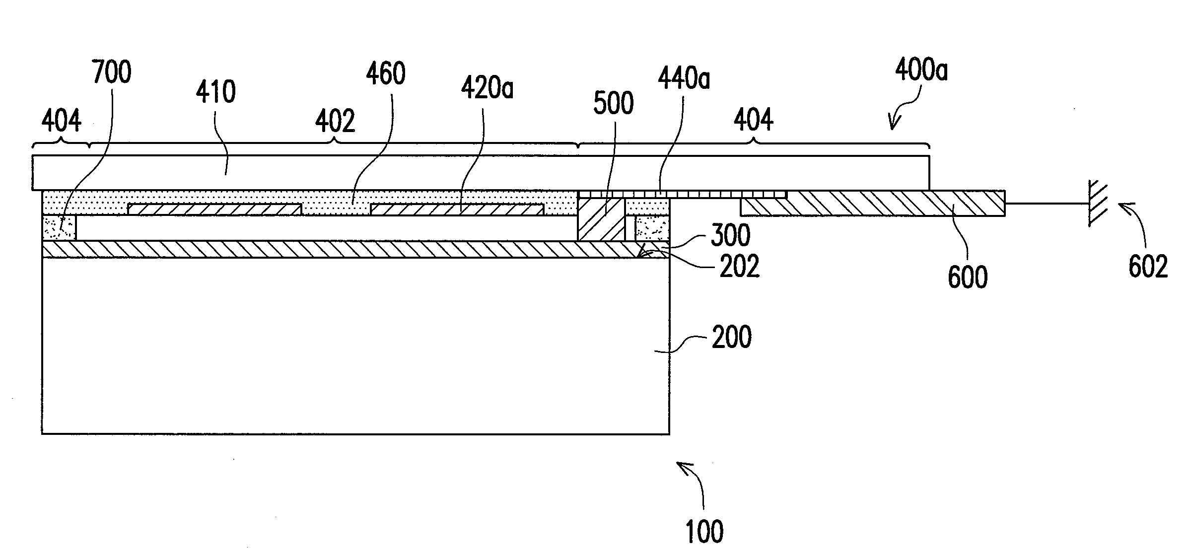
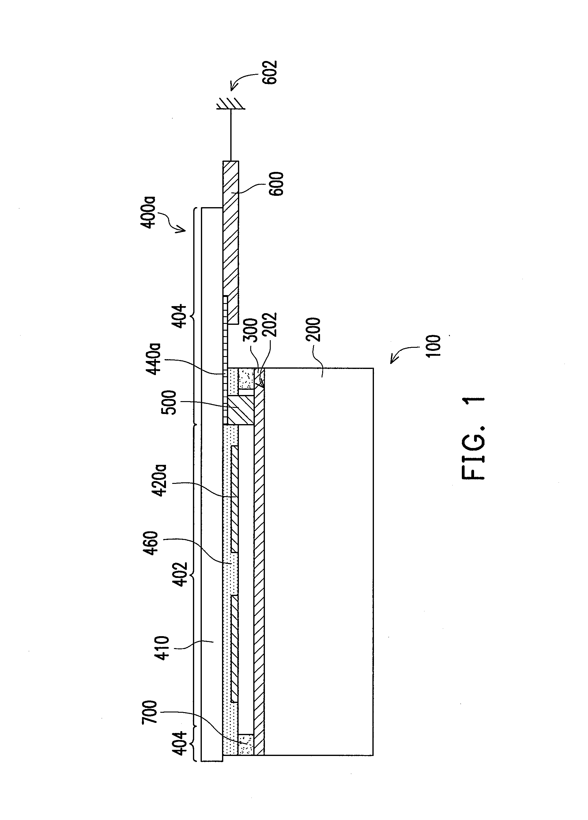
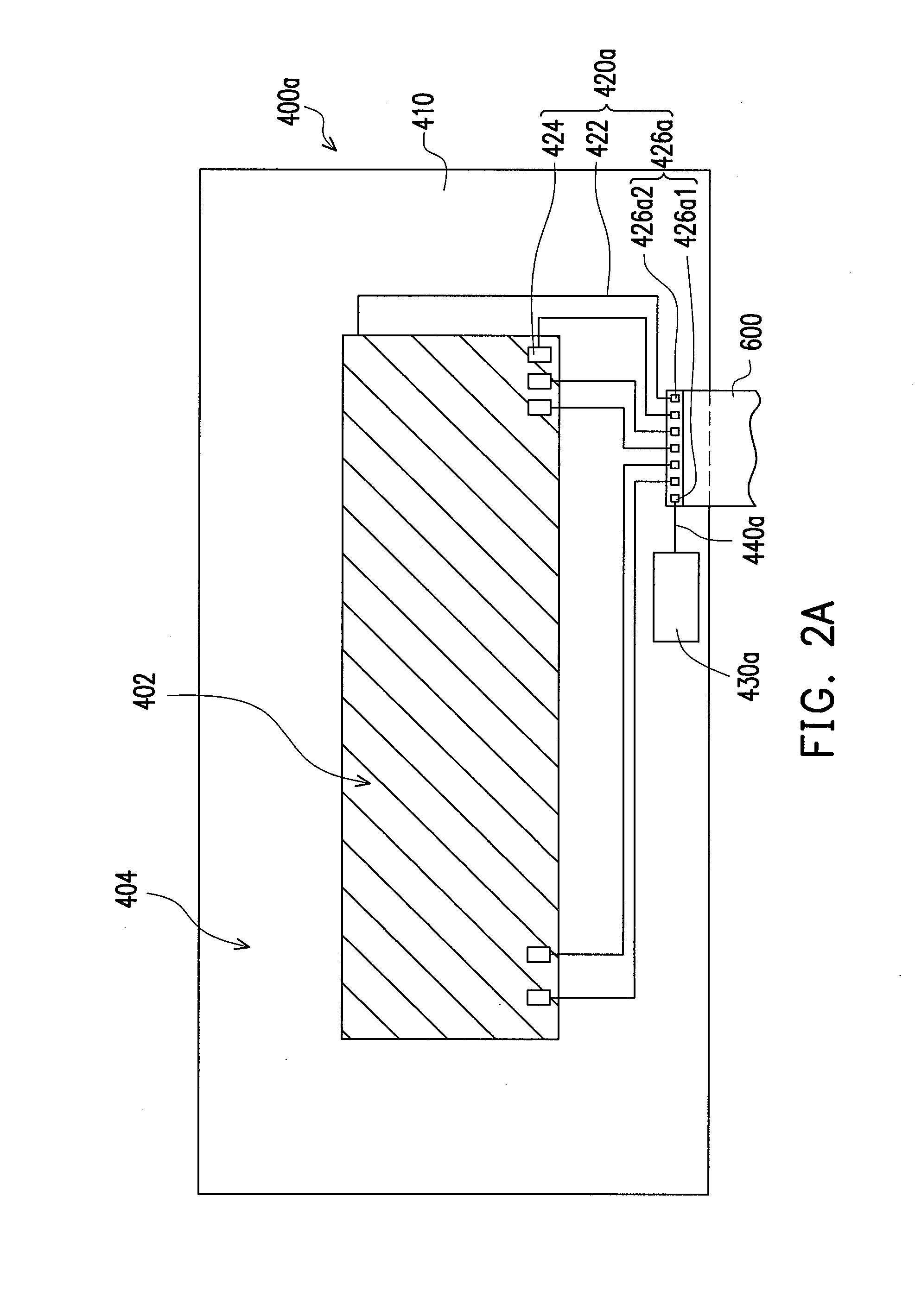
[0030]FIG. 1 is a cross-sectional view of a touch display device according to an embodiment of the invention. FIG. 2A is a bottom view of a touch panel and a flexible circuit board of FIG. 1. Referring to FIG. 1 and FIG. 2A, in the present embodiment, the touch display device 100 includes a display panel 200, a shielding electrode layer 300, a touch panel 400a, a conductive element 500 and a flexible circuit board 600.

[0031]In detail, the display panel 200 has a top surface 202. The display panel 200 is, for example, a transmissive display panel, a trans-reflective display panel, a reflective display panel, a vertical alignment (VA) display panel, an in plane switch (IPS) display panel, a multi-domain vertical alignment (MVA) display panel, a twist nematic (TN) display panel, a fringe field switching (FFS) display panel or an organic light-emitting diode (OLED) display panel, which is not limited by the invention.

[0032]The shielding electrode layer 300 is disposed on the display pan...


PUM


Abstract

A touch display device including a display panel, a shielding electrode layer, a touch panel, a conductive element and a flexible circuit board is provided. The shielding electrode layer covers a top surface of the display panel. The touch panel disposed on the shielding electrode layer includes a substrate, a touch control element, a ground electrode and a metal wire. The touch control element includes a sensing electrode, a transmission wire and two pads. The transmission wire is electrically connected to the sensing electrode and one pad. The meal wire is connected between the ground electrode and the other pad. The shielding electrode layer is electrically connected to the metal wire or the ground electrode of the touch panel through the conductive element. The flexible circuit board is electrically connected to the pads, so that the sensing electrode and the metal wire are electrically connected to the flexible circuit board.

Description

CROSS-REFERENCE TO RELATED APPLICATION[0001]This application claims the priority benefit of China application serial no. 201210052065.1, filed on Mar. 1, 2012. The entirety of the above-mentioned patent application is hereby incorporated by reference herein and made a part of this specification.BACKGROUND OF THE INVENTION[0002]1. Field of the Invention[0003]The invention relates to a display device. Particularly, the invention relates to a touch display device.[0004]2. Description of Related Art[0005]A phenomenon of electrostatic discharge can be seen everywhere in the daily living environments. Since the electron has different affinities for various objects, when any two objects are separated after contacting, it is easy to produce a phenomenon of charge transfer between the objects, which results in accumulation of static electricity. Once the static electricity in the object is accumulated to a certain degree, when the object carrying the static electricity contacts or approaches...

Claims


Application Information

Patent Timeline
IPC IPC(8): G06F3/041
CPCG06F2203/04107G06F3/044G06F2203/04111G06F3/0445G06F3/0446
Inventor YU, CHIA-HUAWU, HSU-HOLIU, HSUAN-CHEN
Owner HANNSTAR DISPLAY CORPORATION
Why Eureka
Try Eureka