Video signal processing apparatus and video signal processing method

Inactive Publication Date: 2013-09-05
PANASONIC CORP
View PDF2 Cites 12 Cited by
  • Summary
  • Abstract
  • Description
  • Claims
  • Application Information

AI Technical Summary

Benefits of technology

The present invention provides a video signal processing apparatus and method that can correct crosstalk and improve image brightness simultaneously. This means that video signals can be processed to reduce differences in luminance that occur naturally in certain areas of the image. This improves the overall quality of the video image and enhances clarity and detail.

Problems solved by technology

It is known that in a video signal processing apparatus capable of displaying a stereoscopic image on a display using a stereoscopic image signal in which right-eye and left-eye images having a parallax alternate every frame, the interference of an image due to the incapability to completely separate the right-eye and left-eye images from each other, that is, crosstalk, often occurs in the stereoscopic image.
In this case, however, the transmittance of the 3D glasses reduces the luminance.
In addition, in the conventional technique disclosed in Patent Literature 1, if a video signal, which is affected by crosstalk, is a signal of a dark image having a low luminance, it is not possible to remove crosstalk components in advance, which leaves crosstalk.

Method used


Image

  • Video signal processing apparatus and video signal processing method
  • Video signal processing apparatus and video signal processing method
  • Video signal processing apparatus and video signal processing method

Examples


first embodiment

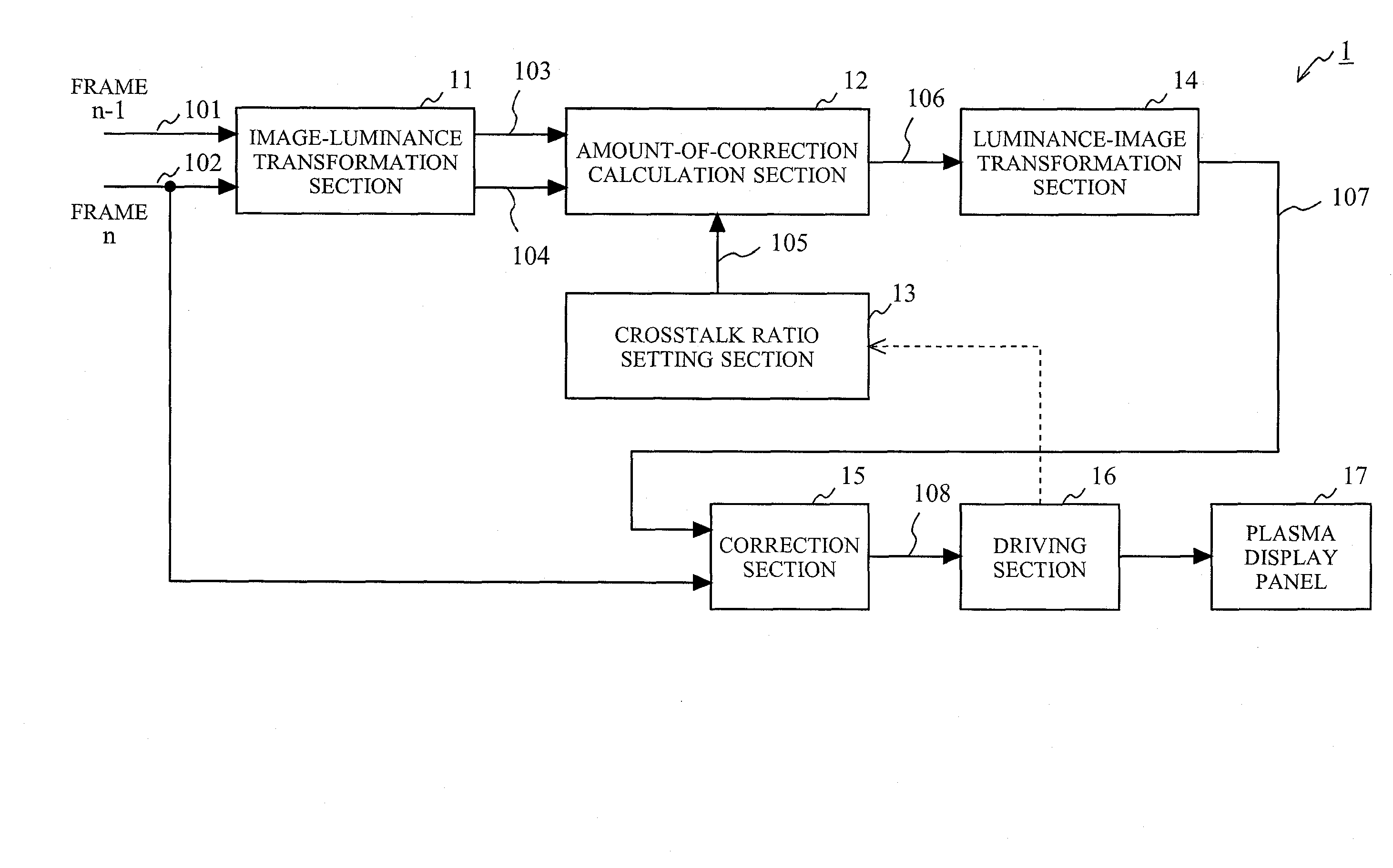
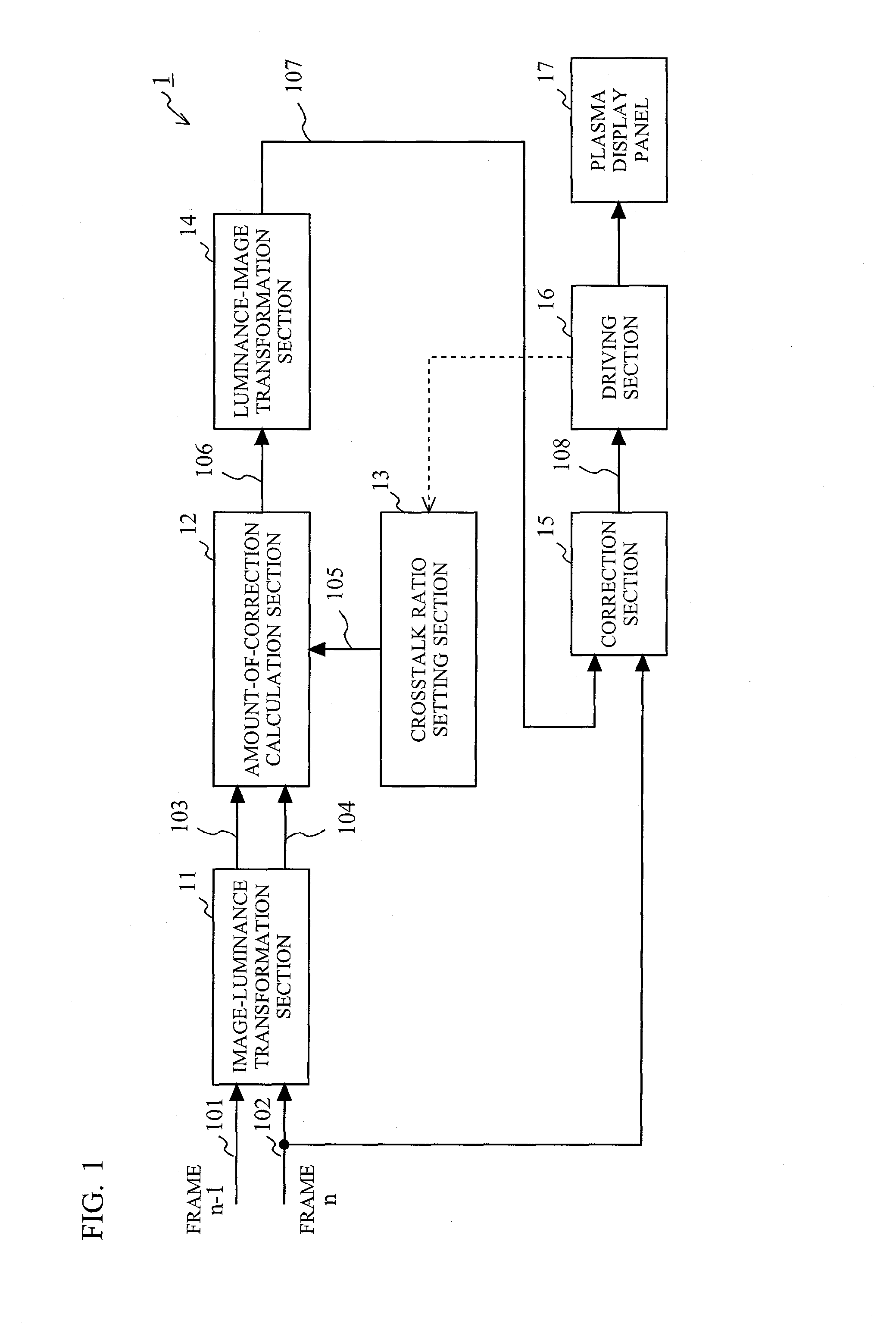
[0027]FIG. 1 is a functional block diagram showing the main configuration of a video signal processing apparatus 1 according to a first embodiment of the present invention. As shown in FIG. 1, the video signal processing apparatus 1 according to the first embodiment includes an image-luminance transformation section 11, an amount-of-correction calculation section 12, a crosstalk ratio setting section 13, a luminance-image transformation section 14, a correction section 15, a driving section 16, and a plasma display panel 17.

[0028]First, the outline of the video signal processing apparatus 1 is described.

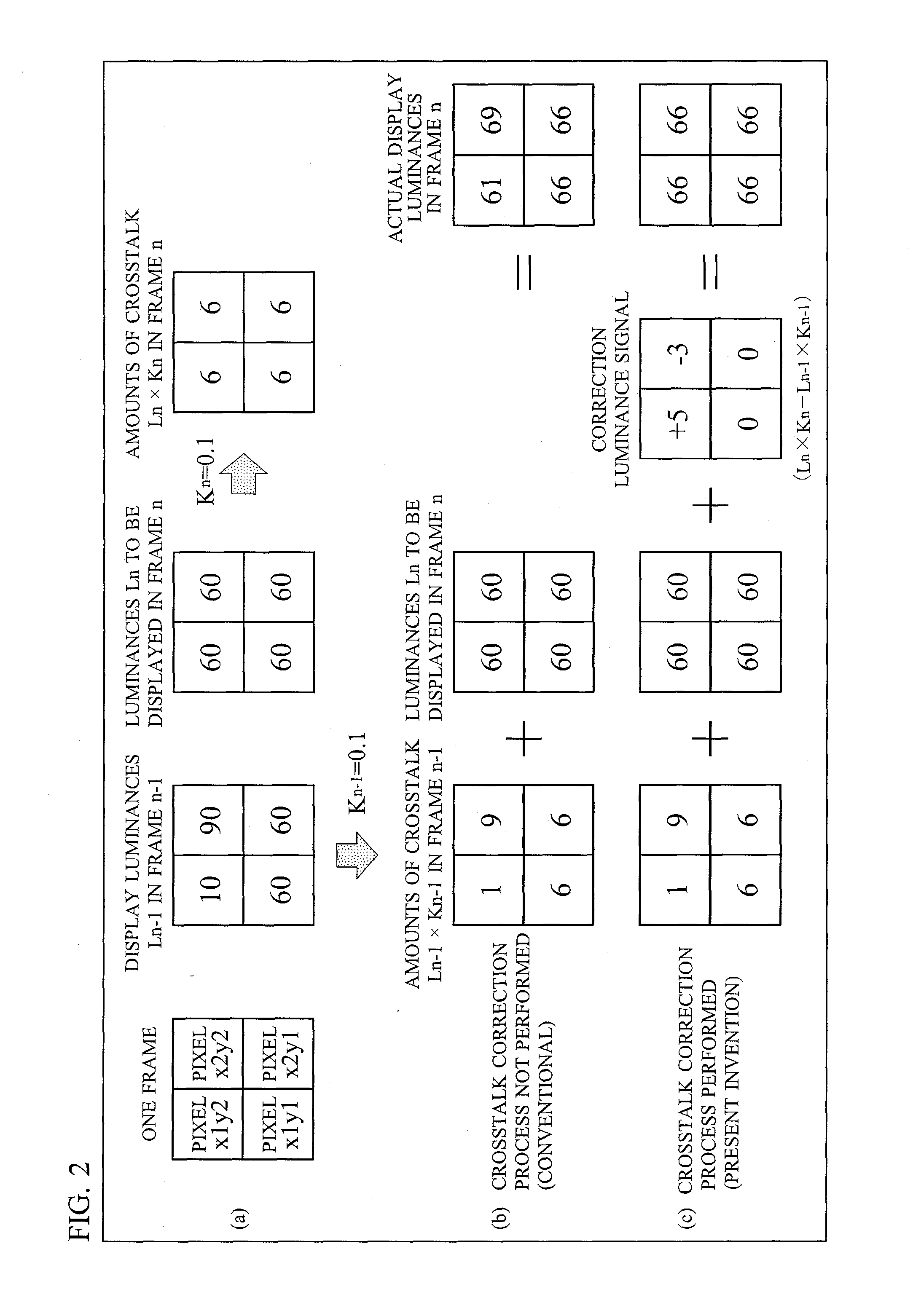
[0029]The video signal processing apparatus 1 according to the first embodiment of the present invention receives a video signal for stereoscopic display in which right-eye and left-eye images having a parallax alternate every frame; performs a crosstalk correction process, which characterizes the present invention, between two successive frames; and then successively outputs the rig...

second embodiment

[0072]FIG. 4 is a functional block diagram showing the main configuration of a video signal processing apparatus 2 according to a second embodiment of the present invention. As shown in FIG. 4, the video signal processing apparatus 2 according to the second embodiment includes an image-luminance transformation section 21, an amount-of-correction calculation section 22, a crosstalk ratio setting section 13, a maximum-amount-of-crosstalk retention section 28, a luminance-image transformation section 14, a correction section 15, a driving section 16, and a plasma display panel 17.

[0073]As shown in FIG. 4, the video signal processing apparatus 2 according to the second embodiment is different from the video signal processing apparatus 1 according to the first embodiment in the image-luminance transformation section 21, the amount-of-correction calculation section 22, and the maximum-amount-of-crosstalk retention section 28. It should be noted that the other components of the video signa...

third embodiment

[0093]The crosstalk correction process according to the first embodiment described above is a balanced process in view of the correction of the amounts of crosstalk, the improvement of the brightness of an image, and the improvement of the contrast of the image. In the crosstalk correction process according to the first embodiment, however, there is a case where the amounts of crosstalk are corrected by subtracting luminance values. Thus, if an image has an extremely low luminance, it may not be possible to subtract correction luminance values from the amounts of crosstalk. Consequently, it may be desirable that, for example, an image having an extremely low luminance should be subjected to the crosstalk correction process according to the second embodiment.

[0094]To that end, in this third embodiment, a description is given of the technique of switching between the crosstalk correction process according to the first embodiment and the crosstalk correction process according to the se...


PUM


Abstract

An image-luminance transformation section receives a video signal on a frame basis, and transforms the video signal into a luminance signal in each frame. A crosstalk ratio setting section sets a crosstalk ratio. An amount-of-correction calculation section calculates a correction luminance signal, for correcting a video signal of a frame n, using a luminance signal of a frame n−1, a luminance signal of the frame n, and the crosstalk ratio. A luminance-image transformation section transforms the correction luminance signal into a correction video signal. A correction section adds the correction video signal to the video signal of the frame n to generate a video signal of the frame n in which the amounts of crosstalk have been corrected.

Description

BACKGROUND OF THE INVENTION[0001]1. Field of the Invention[0002]The present invention relates to a video signal processing apparatus and a video signal processing method, and in particular, relates to a video signal processing apparatus for processing a stereoscopic image signal in order to display a stereoscopic image on a display, and to a video signal processing method.[0003]2. Description of the Background Art[0004]It is known that in a video signal processing apparatus capable of displaying a stereoscopic image on a display using a stereoscopic image signal in which right-eye and left-eye images having a parallax alternate every frame, the interference of an image due to the incapability to completely separate the right-eye and left-eye images from each other, that is, crosstalk, often occurs in the stereoscopic image.[0005]As a conventional technique for solving such a problem, a method of suppressing crosstalk is known (see Japanese Laid-Open Patent Publication No. 8-331600 (...

Claims


Application Information

Patent Timeline
IPC IPC(8): H04N13/04H04N13/122
CPCH04N13/0018H04N13/122
Inventor YANO, NATSUMIIWAKURA, NORIYUKI
Owner PANASONIC CORP
Why Eureka
Try Eureka