Illumination lens for short-throw lighting

a technology of illumination lens and short-throw lighting, applied in the field of wide-angle illumination pattern, can solve the problems of inability to meet the needs of wide-angle illumination, difficult uniformity, and not all of this art, however, was suitable for ultra-thin displays

Active Publication Date: 2013-09-05
SEOUL SEMICONDUCTOR
View PDF5 Cites 48 Cited by
  • Summary
  • Abstract
  • Description
  • Claims
  • Application Information

AI Technical Summary

Benefits of technology

[0017]It is the first objective of this invention to disclose numerically-specific lens configurations that in arrays will provide uniform illumination for a close planar target, especially in retail refrigeration displays and in thinnest-possible direct-view LCD backl

Problems solved by technology

Light emitting diodes (LEDs) may generate light in zones so small (a few mm across) that it is a challenge to spread their flux uniformly over a large target zone, especially one is that is much wider than its distance from the LED.
Just as LEDs by themselves may not produce a spotlight beam, and so need collimating lenses, they may be equally unsuitable for wide-angle illumination as well, and so need illumination lenses to do the job.
While fluorescent tubes may be on the backlight perimeter due to their thickness, light-emitting diodes are so much smaller that they can be placed directly behind the LCD display, (so called “direct-view backlight”), but their punctate nature makes uniformity more difficult, prompting a wide range of prior art over the last twenty years.
Not all of this art, however, was suitable for ultra-thin displays.
Also, fluorescent lamps may produce a very non-uniform lighting pattern on the cabinet shelves.
Because fluorescent tubes radiate in all directions instead of just upon the shelves, much of their light is wasted.
This is the advantage of the last approach, but free-form lenses generating rectangular patterns have proved difficult to produce, via injection moldin

Method used


Image

  • Illumination lens for short-throw lighting
  • Illumination lens for short-throw lighting
  • Illumination lens for short-throw lighting

Examples


Embodiment Construction

[0042]The invention is described more fully hereinafter with reference to the to accompanying drawings, in which embodiments of the invention are shown. This invention may, however, be embodied in many different forms and should not be construed as limited to the embodiments set forth herein. Rather, these embodiments are provided so that this disclosure is thorough, and will fully convey the scope of the invention to those skilled in the art. In the drawings, the size and relative sizes of layers and regions may be exaggerated for clarity Like is reference numerals in the drawings denote like elements.

[0043]It will be understood that when an element or layer is referred to as being “on” or “connected to” another element or layer, it can be directly on or directly connected to the other element or layer, or intervening elements or layers may be present. In contrast, when an element is referred to as being “directly on” or “directly connected to” another element or layer, there are n...


PUM


Abstract

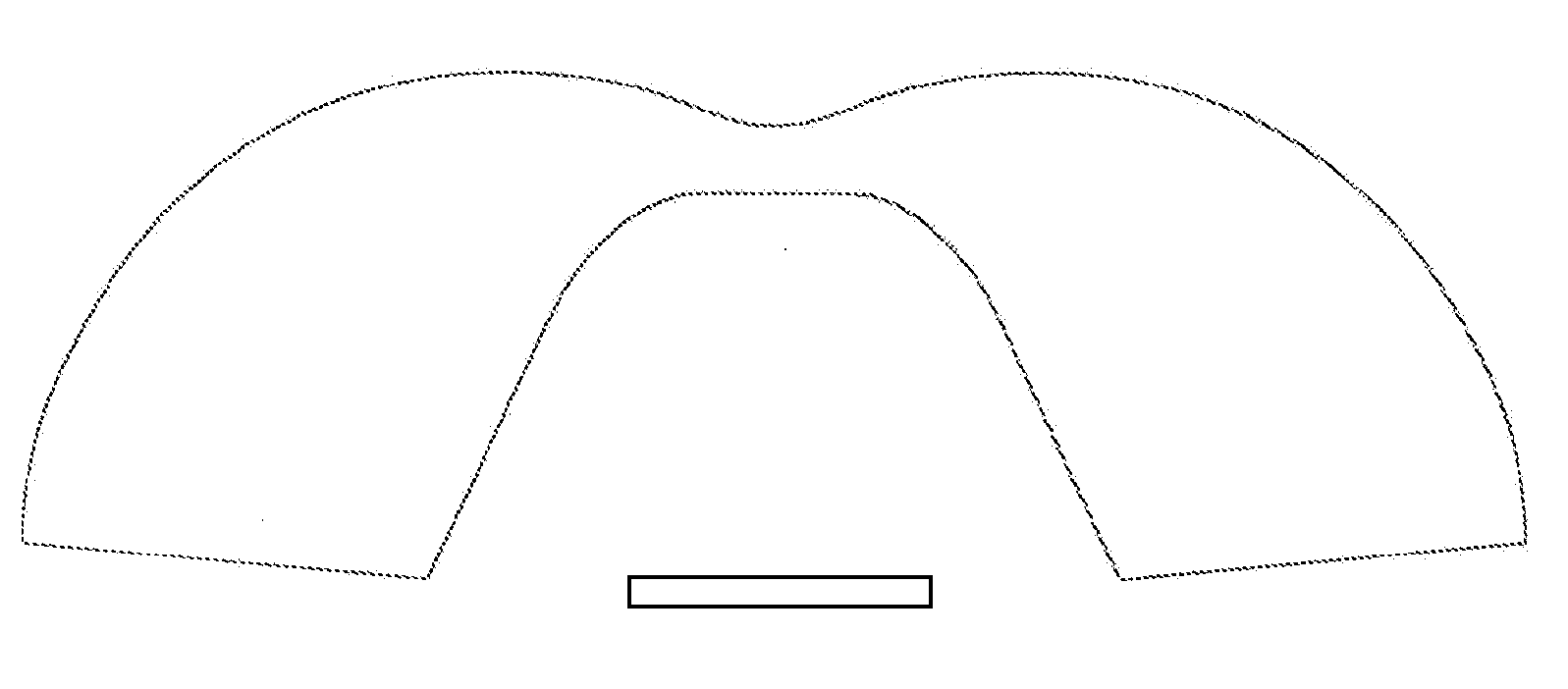
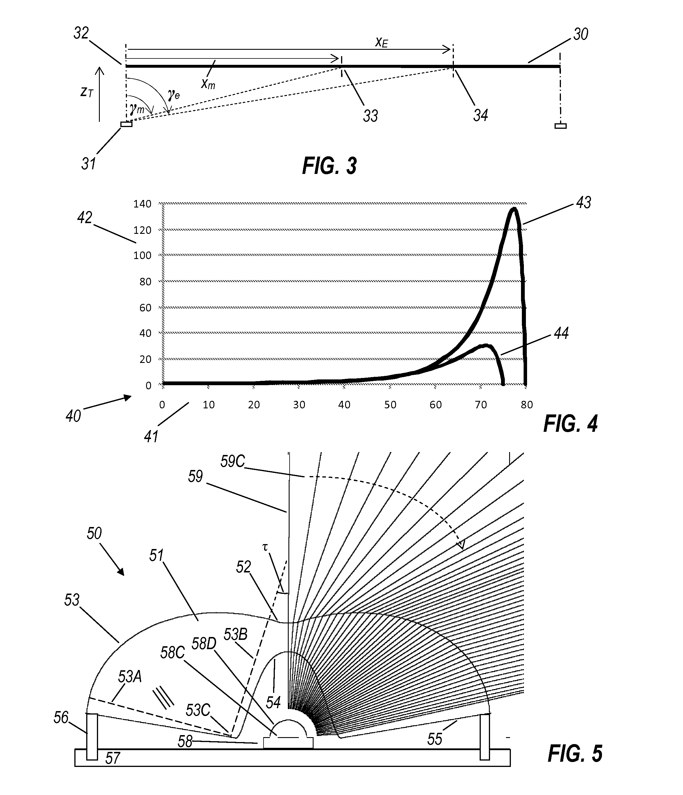
Exemplary embodiments of the present invention relate to wide-angle illumination patterns for short-throw lighting. An illumination lens according to an exemplary embodiment includes a light incident surface that defines a cavity and has a flat top and lateral flanks, the light incident surface being configured to receive light from an underlying light emitting element. The illumination lens also includes a light exiting surface having a central indentation and a surrounding toroid, wherein the flat top faces the central indentation.

Description

CROSS-REFERENCE TO RELATED APPLICATION[0001]This application claims the benefit of U.S. Provisional Patent Application No. 61 / 606,710, filed on Mar. 5, 2012, which is hereby incorporated by reference for all purposes as if fully set forth herein.BACKGROUND[0002]1. Field[0003]Exemplary embodiments of the present invention relate to wide-angle illumination patterns suitable for short-throw lighting, and a general design method for generating their surface profiles.[0004]2. Discussion of the Background[0005]Light emitting diodes (LEDs) may generate light in zones so small (a few mm across) that it is a challenge to spread their flux uniformly over a large target zone, especially one is that is much wider than its distance from the LED. So-called short-throw lighting, of close targets, is the polar opposite of spot lighting, which aims at distant targets. Just as LEDs by themselves may not produce a spotlight beam, and so need collimating lenses, they may be equally unsuitable for wide-...

Claims


Application Information

Patent Timeline
IPC IPC(8): F21V5/04F21V13/02
CPCF21W2131/305F21W2131/405F21Y2101/02F25D27/00F21V13/02G02B19/0028G02B19/0061F21V5/04F21Y2115/10F21K9/60
Inventor PELKA, DAVID GPARKYN, WILLIAM A.
Owner SEOUL SEMICONDUCTOR
Why Eureka
Try Eureka