Surface cleaning apparatus
a technology for cleaning apparatus and surface, which is applied in the direction of carpet cleaners, cleaning machines, cleaning equipments, etc., can solve the problems of hindering the user's visual ascertainment of damp cleaning pads may not completely remove soil on the surface, and it is difficult for users to ascertain the liquid level within the reservoir
- Summary
- Abstract
- Description
- Claims
- Application Information
AI Technical Summary
Benefits of technology
Problems solved by technology
Method used
Image

Examples
first embodiment
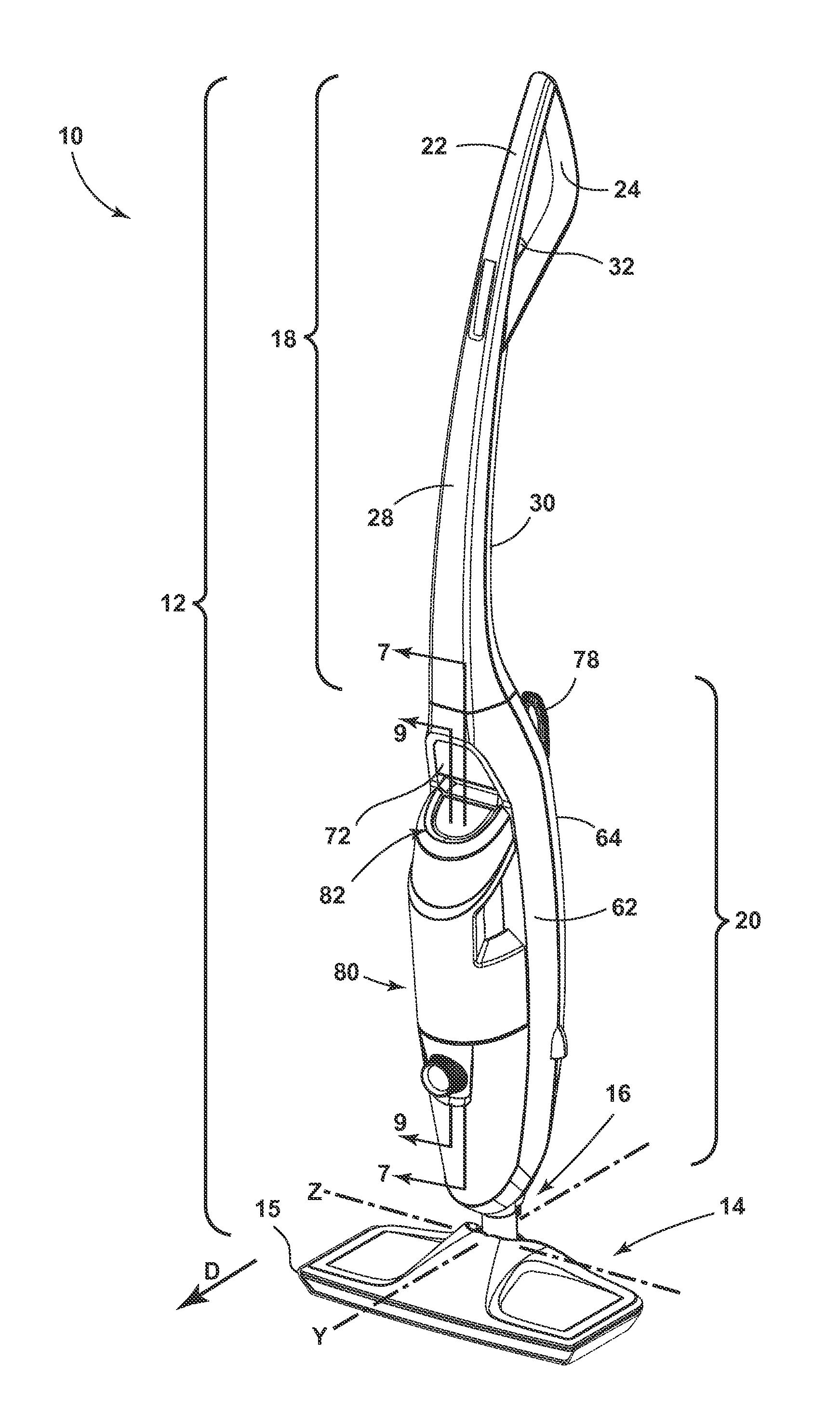
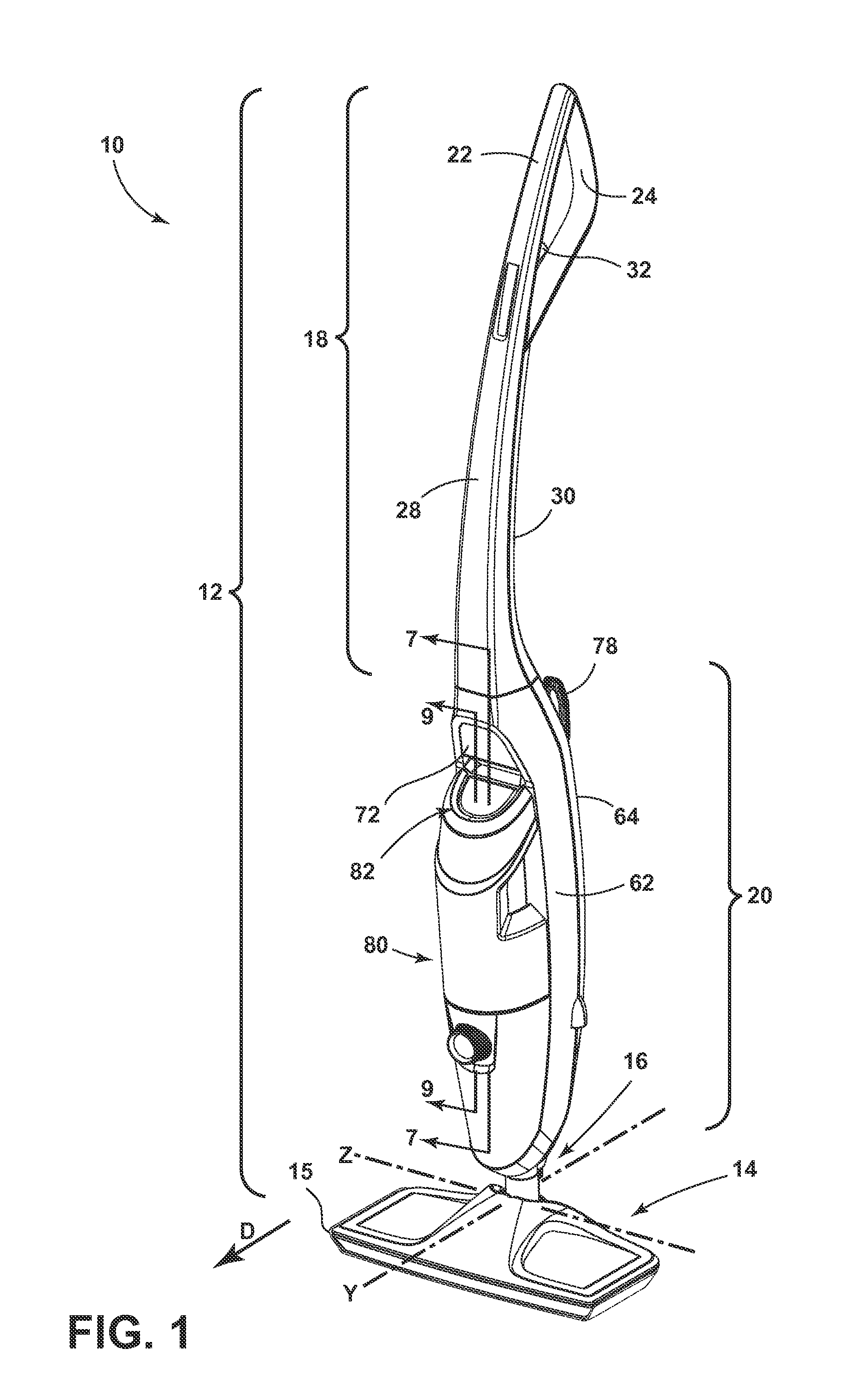
[0043]Referring to the drawings, and in particular to FIGS. 1-2, a surface cleaning apparatus according to the invention comprises a steam mop 10 having a housing with an upright handle assembly 12 and a foot assembly 14. A cleaning pad 15 can be selectively received on the foot assembly 14 for wiping a surface to be cleaned.
[0044]The foot assembly 14 is swivelably mounted to the handle assembly 12 via a coupling joint 16. The handle assembly 12 can pivot from an upright, stored position, in which the handle assembly 12 is oriented substantially vertical relative to the surface to be cleaned, to a reclined, use position, in which the handle assembly 12 is pivoted rearwardly relative to the foot assembly 14 to form an acute angle with the surface to be cleaned. The coupling joint 16 can comprise a ball joint, or a universal or a Cardan joint, as further disclosed in U.S. Conventional patent application Ser. No. 12 / 778,615, U.S. Pat. No. 4,971,471 and Chinese Patent No. CN2482956, whi...
second embodiment
[0083]A surface cleaning apparatus according to the invention is shown in FIGS. 11-16. Because many of the components of this embodiment are similar to the previous embodiment, like features are indicated with the same reference numeral bearing a prime (′) symbol. Any of the previously described features, including LED illumination components, can be incorporated into the following embodiment of the invention.
[0084]The surface cleaning apparatus comprises a steam mop 400 with an upright handle assembly 12′ that is substantially similar to the previous embodiment. The upright handle assembly 12′ is swivelably mounted to a foot assembly 402 through a coupling joint 16′. A cleaning pad 15′ can be selectively received on the foot assembly 402 for wiping a surface to be cleaned. The coupling joint 16′ can comprises a multi-axis Cardan joint as shown in the figures, but can alternatively comprise a ball joint to swivelably connect the foot assembly 402 to the upright handle assembly 12′. ...
third embodiment
[0098]A surface cleaning apparatus, illustrated as a steam mop 500, according to the invention is shown in FIGS. 17-30. Because many of the components of this embodiment are similar to the previous embodiments, like features are indicated with the same reference numerals. Any of the previously described features can be incorporated into the following embodiment of the invention. The coupling joint 16 swivelably mounts the handle assembly 12 to the foot assembly 14 and is configured to permit the handle assembly 12 to rotate about more than one axis relative to the foot assembly 14 when the handle assembly 12 is in the reclined use position. As shown herein, the coupling joint 16 can comprise a universal or Cardan joint, and can be configured to permit the foot assembly 14 to swivel multi-axially relative to the handle assembly 12. In this embodiment, the coupling joint 16 is configured to rotate back and forth about horizontal axis Z, which extends laterally through the sides of the...
PUM
| Property | Measurement | Unit |
|---|---|---|
| Transparency | aaaaa | aaaaa |
| Light | aaaaa | aaaaa |
Abstract
Description
Claims
Application Information
 - Generate Ideas
- Intellectual Property
- Life Sciences
- Materials
- Tech Scout
- Unparalleled Data Quality
- Higher Quality Content
- 60% Fewer Hallucinations
Browse by: Latest US Patents, China's latest patents, Technical Efficacy Thesaurus, Application Domain, Technology Topic, Popular Technical Reports.
© 2025 PatSnap. All rights reserved.Legal|Privacy policy|Modern Slavery Act Transparency Statement|Sitemap|About US| Contact US: help@patsnap.com