Pipette

a pipette and pipette technology, applied in the field of pipette, can solve the problems of high manufacturing cost and impaired precision of calibration, and achieve the effects of reducing manufacturing costs, reducing errors, and improving calibration precision

Active Publication Date: 2013-09-12
EPPENDORF SE
View PDF0 Cites 14 Cited by
  • Summary
  • Abstract
  • Description
  • Claims
  • Application Information

AI Technical Summary

Benefits of technology

[0028]In order to drive the relocatable screw element, the latter has a toothing on the upper edge with teeth which are directed parallel to the instantaneous axis of the relocatable screw element. The toothing runs along a helical line which has the same pitch as that of the thread of the relocatable screw element which engages into the thread of the stationary screw element. The toothed driving wheel, rotatably mounted on a bearing that is fixedly connected to the casing, is engaged with the toothing. When the toothed driving wheel is being rotated by means of the means for rotating, the relocatable screw element is screwed in the stationary screw element and axially relocated through this. In that the toothing of the relocatable screw element runs along a helical line having the same pitch as the thread of the relocatable screw element, the toothing remains in engagement with the toothed driving wheel. Due to this construction, component parts are saved compared to the conventional means for calibration by the user. Error sources are reduced through this, and the precision of the calibration is improved. Moreover, the expense for manufacture and the production cost are reduced.
[0029]According to one embodiment, the relocatable screw element is a threaded ring, disposed concentrically to the lifting rod and having a thread on the circumference, which has the toothing at the topside and rests on the lower stop body at the downside. The threaded ring can be housed in the casing in a space-saving manner, and it can uniformly rest on the lower stop body with its lower edge.
[0030]According to a further embodiment, the stationary screw element is a hollow cylindrical lifting body which has an external thread at the outer circumference to which an internal thread on the inner circumference of the threaded ring is engaged, the lifting body has several axially extending slots, the lower stop body is arranged in the lifting body and the lower stop body has several outwardly projecting projections which grip through the slots and have portions that jut out of the lifting body and on which the threaded ring is seated. A space-saving arrangement of the stationary screw element and the lower stop body is made possible through this.
[0031]According to a further embodiment, the overstroke spring support is disposed in the lifting body, and the overstroke spring is disposed in the lifting body between the lower stop body and the overstroke spring support. Overstroke spring support and overstroke spring are accommodated in a space-saving manner through this. In addition, the lifting body serves as a receiver and as a carrier for the overstroke spring support and the overstroke spring in a space-saving manner.
[0033]According to a further embodiment, the lifting body is fixedly connected to the spindle nut at the topside. This permits a space-saving housing of the means for adjusting the metering volume. The lifting body serves as a seat and as a carrier for nut, spindle and lifting rod, which is inserted into the upper passage hole and can be relocated between the upper and the lower stop body with the stop element.
[0043]By way of example, the limit is a radially projecting projection of the relocatable screw element which hits a projection that is fixedly disposed in the casing when the toothed drive wheel reaches the highest tooth of the toothing. According to a preferred embodiment, the toothing of the relocatable screw element is limited by an axial projection next to the highest tooth, which blocks the toothed drive wheel at the end of the axial toothing. In order to block the toothed drive wheel, the axial projection has no teeth and is made so massively that the toothed drive wheel cannot be rotated beyond it. When the toothed drive wheel engages into the deepest tooth of the toothing, further rotation of the relocatable screw element is prevented by the step which the toothing has towards the neighbouring highest tooth.

Problems solved by technology

In the known device for user calibration, the precision of the calibration is impaired due to manufacture tolerances and wear of the many component parts.
Moreover, the manufacturing expense is high due to the many component parts.

Method used


Image

  • Pipette
  • Pipette
  • Pipette

Examples


Embodiment Construction

[0056]While this invention may be embodied in many different forms, there are described in detail herein a specific preferred embodiment of the invention. This description is an exemplification of the principles of the invention and is not intended to limit the invention to the particular embodiment illustrated.

[0057]In the present application, the designations “up” and “down”, “above” and “below” and “horizontal” and “vertical” refer to an orientation of the pipette in which the casing is oriented vertically downward with the seat. In this orientation, a pipette point fastened on the seat can be directed towards a vessel situated there under, in order to aspirate or to deliver a liquid.

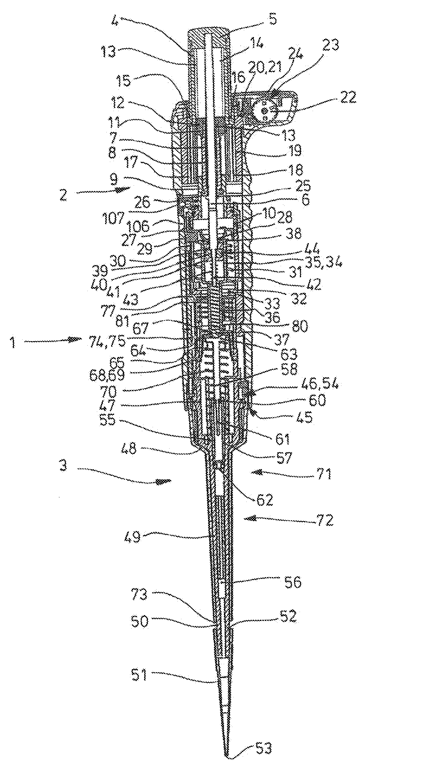
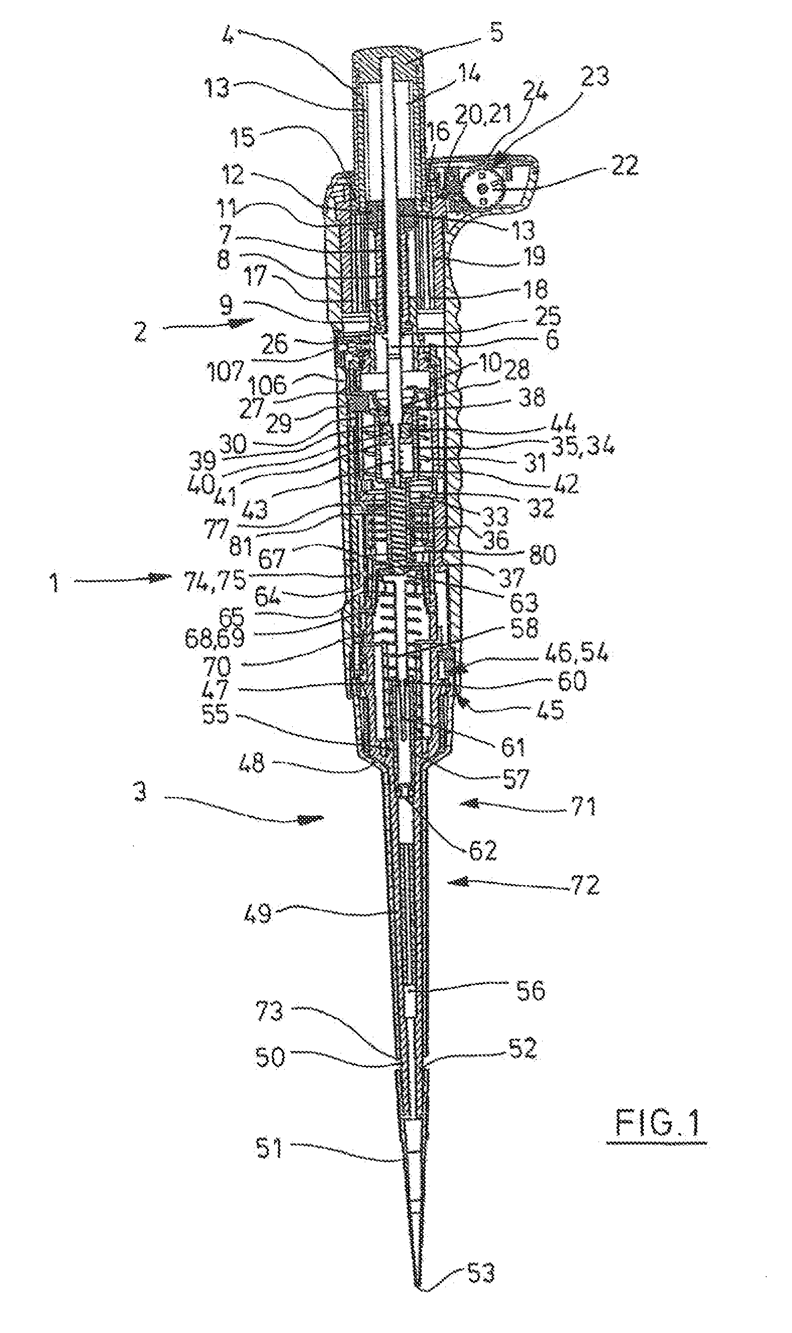
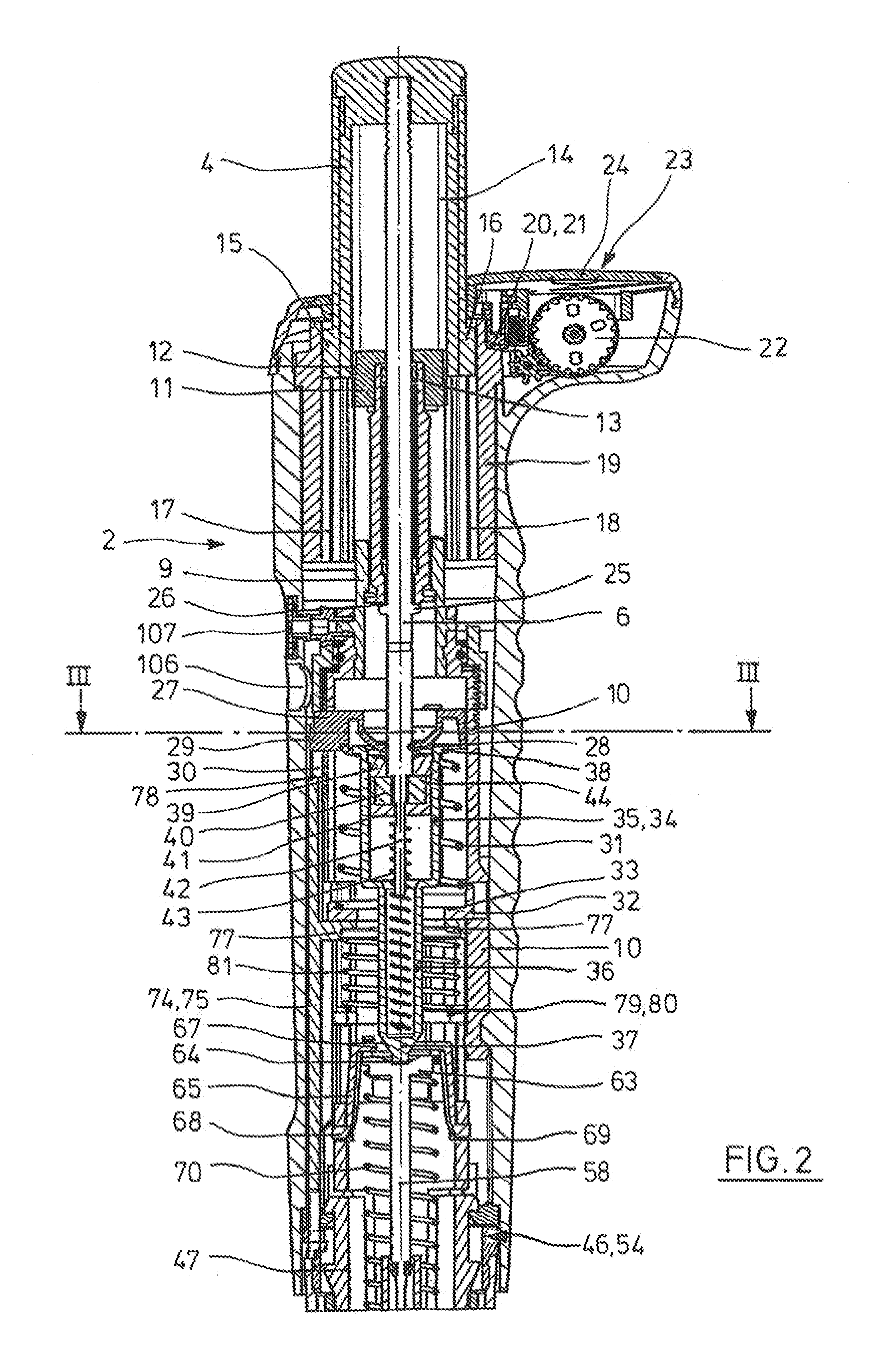
[0058]According to FIGS. 1 and 2, the pipette 1 has a rod-shaped casing, formed as a handle, with an upper part 2 of the casing and a lower part 3 of the casing. The upper part 2 of the casing forms a drive unit with all the components contained therein, and the lower part 3 of the casing a displacer...


PUM


Abstract

A pipette with a rod-shaped casing, a seat, a displacement equipment, comprising a displacement chamber with a relocatable limit, a connection channel, a drive equipment for relocating the relocatable limit of the displacement chamber, coupled to the relocatable limit and having an axially relocatable lifting rod, an upper stop body, a lower stop body and a stop element on the circumference of the lifting rod for limiting the stroke of the lifting rod, an overstroke spring, a stationary screw element, and with a screw element that is relocatable in the casing, a toothing, running along a helical line with the same pitch as that of the thread of the relocatable screw element and having teeth on the upper edge of the relocatable screw element that are directed in the direction of the instantaneous axis of the relocatable screw element, a toothed driving wheel, and means for rotating the toothed driving wheel.

Description

CROSS-REFERENCE TO RELATED APPLICATIONS[0001]This application claims priority to provisional patent application No. 61 / 604834, filed Feb. 29, 2012.STATEMENT REGARDING FEDERALLY SPONSORED RESEARCH[0002]Not applicableBACKGROUND OF THE INVENTION[0003]The present invention relates to a pipette for replaceable pipette tips.[0004]Pipettes are used in the laboratory in particular for metering liquids. For this purpose, a pipette tip is clamped fast on a seat of the pipette with an upper opening. The seat is mostly a conical or cylindrical projection with respect to a casing of the pipette, onto which a pipette tip can be clamped with the upper opening thereof. The pipette tip can pick up and give out liquid through a lower opening. Air cushion pipettes comprise a displacement equipment for air, which is communicatingly connected to the pipette tip through a hole in the seat. An air cushion is relocated by means of the displacement equipment, so that liquid is sucked into the pipette tip an...

Claims


Application Information

Patent Timeline
Patent Type & Authority Applications(United States)
IPC IPC(8): B01L3/02
CPCB01L3/0224B01L3/021B01L2200/148
Inventor WILMER, JENS
Owner EPPENDORF SE
Why Eureka
Try Eureka