Rotating flow control diverter

Inactive Publication Date: 2013-09-12
WEATHERFORD TECH HLDG LLC
View PDF6 Cites 3 Cited by
  • Summary
  • Abstract
  • Description
  • Claims
  • Application Information

AI Technical Summary

Benefits of technology

The patent text describes a device that rotates a fan ring to circulate lubricating fluid. This helps to prevent wear and tear on the device. The technical effect of this device is to improve its efficiency and lifespan.

Problems solved by technology

If the ability to maintain adequate lubrication of the bearings of a rotating flow control diverter is compromised, the bearings will fail quickly.
A common source of premature bearings failure in rotating flow head technology is the failure of a seal or seal stack that isolates the wellbore environment from entering the bearing assembly housing.
Another major cause of bearing compromise in rotating flow control devices is heat.
The bearing assembly generates considerable heat due to thrust loads on the internal components, particularly when drilling under high well bore pressure.
However, such prior art cooling systems are frequently complex and prone to undesired failure.
Furthermore, the hydraulic system requires equipment and hoses that add to an already crowded work area, and which represent a safety risk to workers in the event of failure.

Method used


Image

  • Rotating flow control diverter
  • Rotating flow control diverter
  • Rotating flow control diverter

Examples


Embodiment Construction

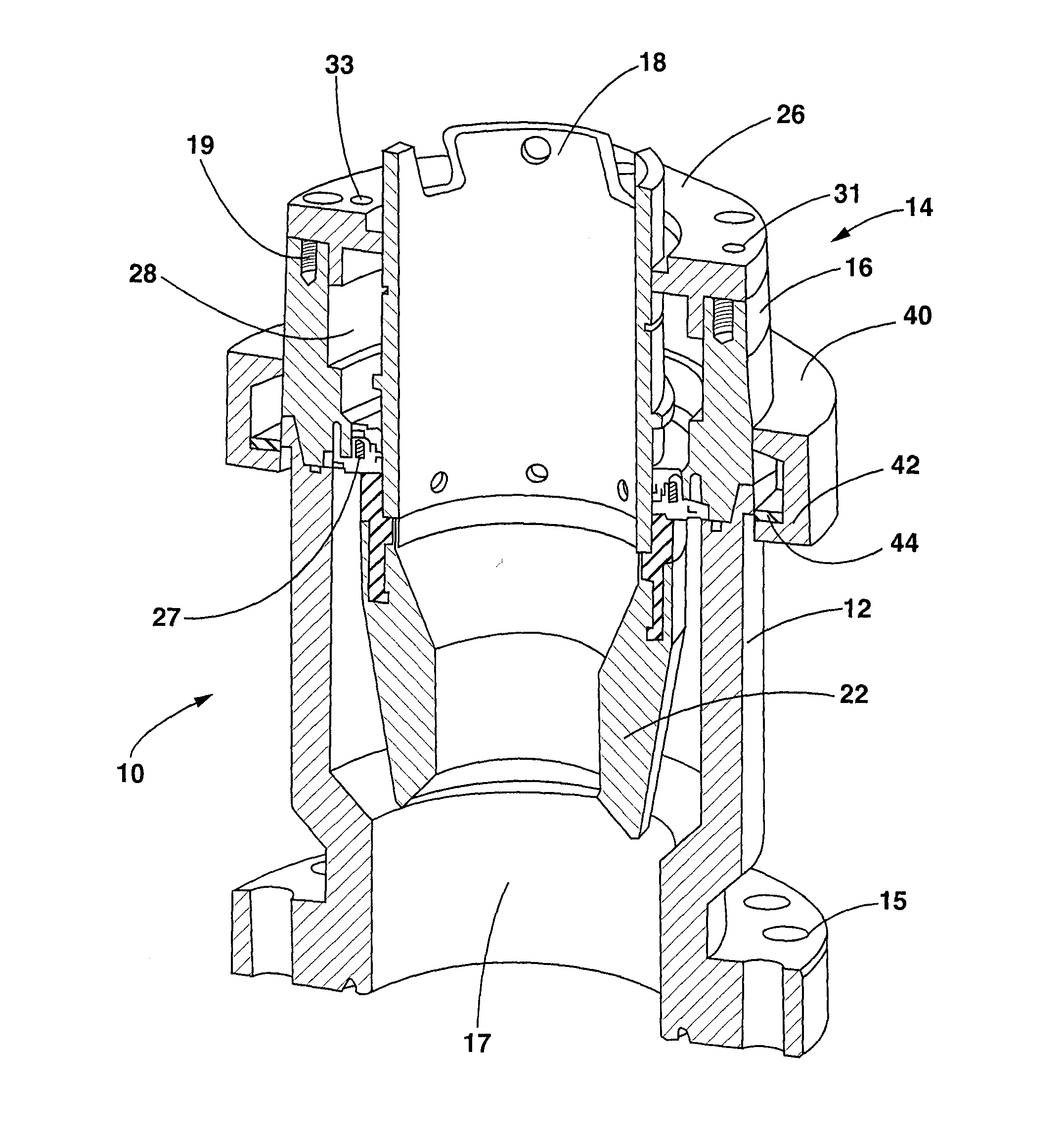
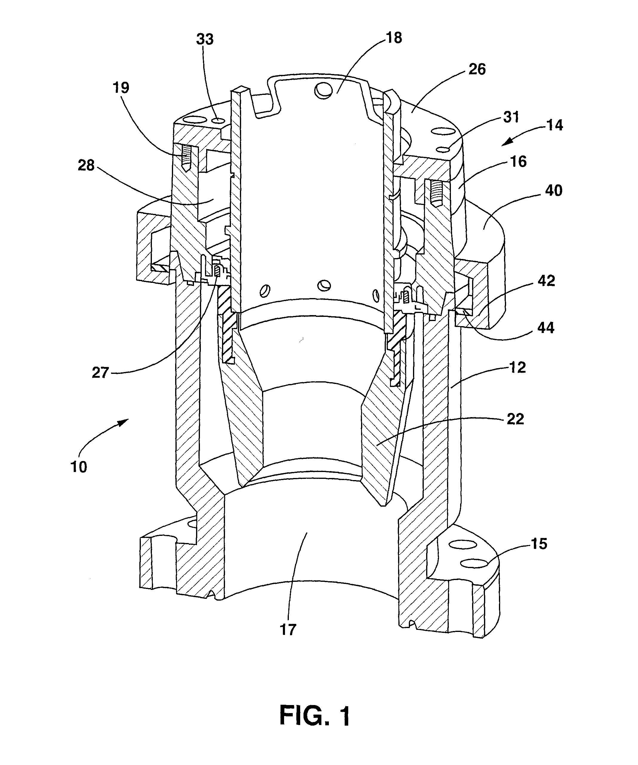
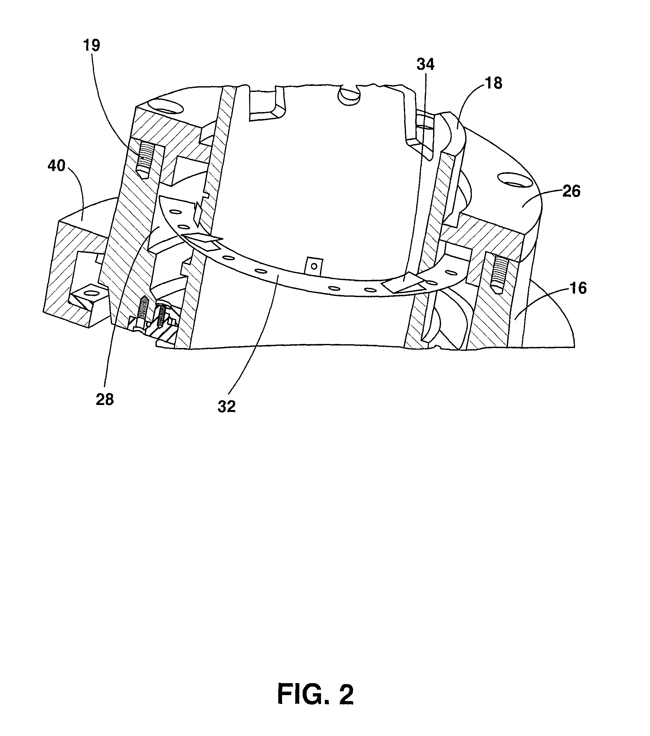
[0065]The invention relates to a novel rotating flow control diverter. When describing the present invention, all terms not defined herein have their common art-recognized meanings. To the extent that the following description is of a specific embodiment or a particular use of the invention, it is intended to be illustrative only, and not limiting of the claimed invention. The following description is intended to cover all alternatives, modifications and equivalents that are included in the spirit and scope of the invention, as defined in the appended claims.

[0066]In this application, the term “lubricating fluid” and “lubricant” are used to interchangeably to refer to the lubricant used to cool and lubricate the bearings of a rotating flow control diverter. It can be understood that the lubricant employed with the present invention may be any suitable fluid lubricant, including, without limit, oil.

[0067]A rotating flow control diverter generally comprises a stationary housing adapte...


PUM


Abstract

The present invention is directed to rotating flow control diverter having sealed bearing assembly that does not require external hydraulic pumping to circulate and cool the lubricating fluid used to lubricated the bearings of the sealed bearing assembly.

Description

FIELD OF THE INVENTION[0001]The invention relates to a wellhead apparatus for well control and more particularly to an apparatus used to control and divert drilling and wellbore fluids and gases, and produced gases and solids during drilling and other operations.BACKGROUND[0002]In the oil and gas industry it is conventional to mount a rotating blowout preventer or rotating flow control diverter at the top of a blowout preventer (BOP) stack beneath the drilling floor of a drilling rig while drilling for oil, gas or coal bed methane. The rotating flow control diverter serves multiple purposes including sealing pipe that is being moved in and out of the wellbore while allowing rotation of same. The rotating flow control diverter may also be used to contain or divert fluids such as drilling mud, produced fluids, and surface injected air or gas into a recovery line.[0003]Typically a rotating flow control diverter consists of rubber strippers or sealing elements and an associated hollow q...

Claims


Application Information

Patent Timeline
IPC IPC(8): E21B33/08
CPCE21B33/085
Inventor BOYD, MICHAEL
Owner WEATHERFORD TECH HLDG LLC
Why Eureka
Try Eureka