
Mobile terminal apparatus and method for performing wireless communication using an indirect feeding antenna

Inactive Publication Date: 2013-09-12
PANTECH CO LTD
View PDF3 Cites 16 Cited by
  • Summary
  • Abstract
  • Description
  • Claims
  • Application Information

AI Technical Summary

Benefits of technology

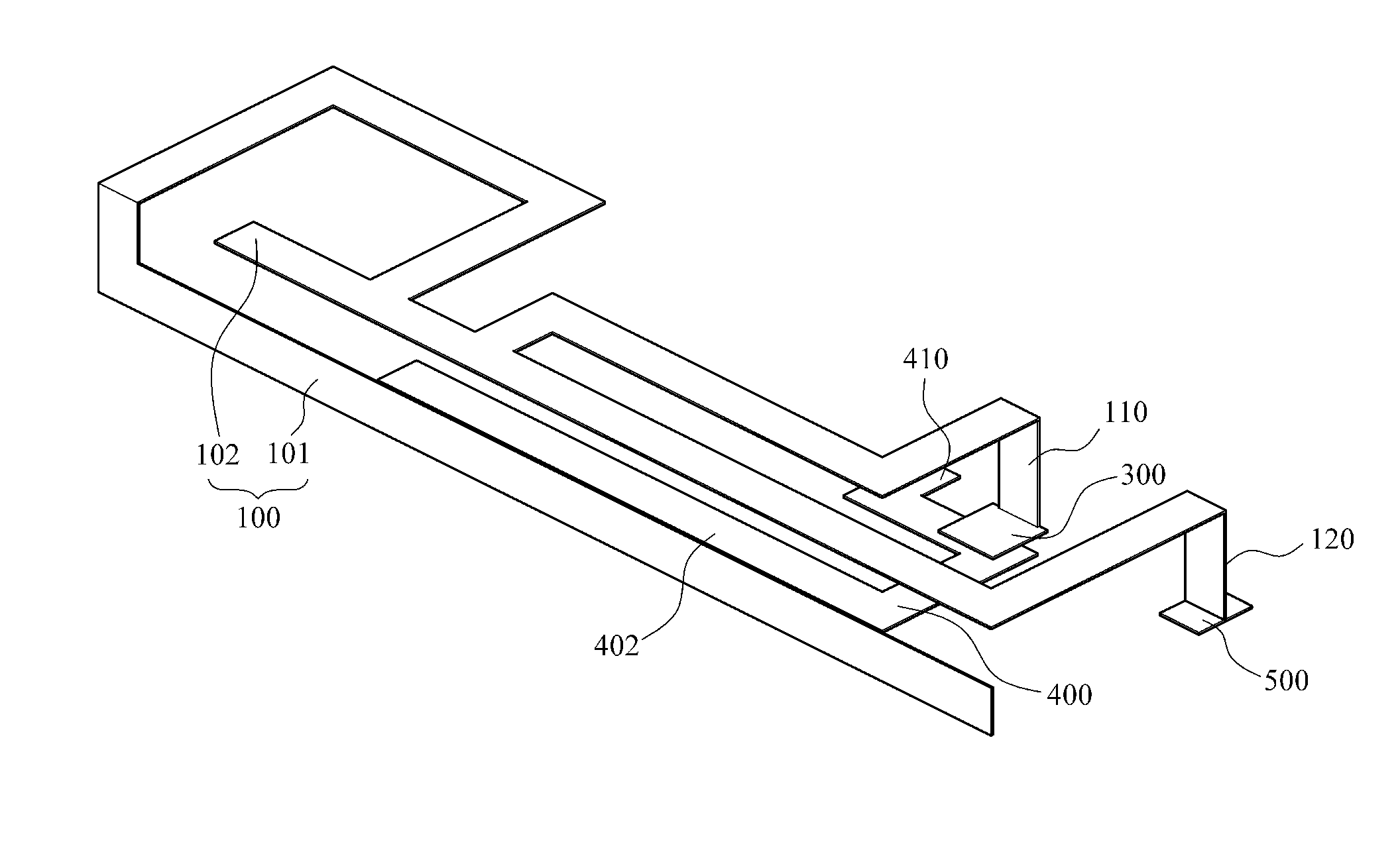
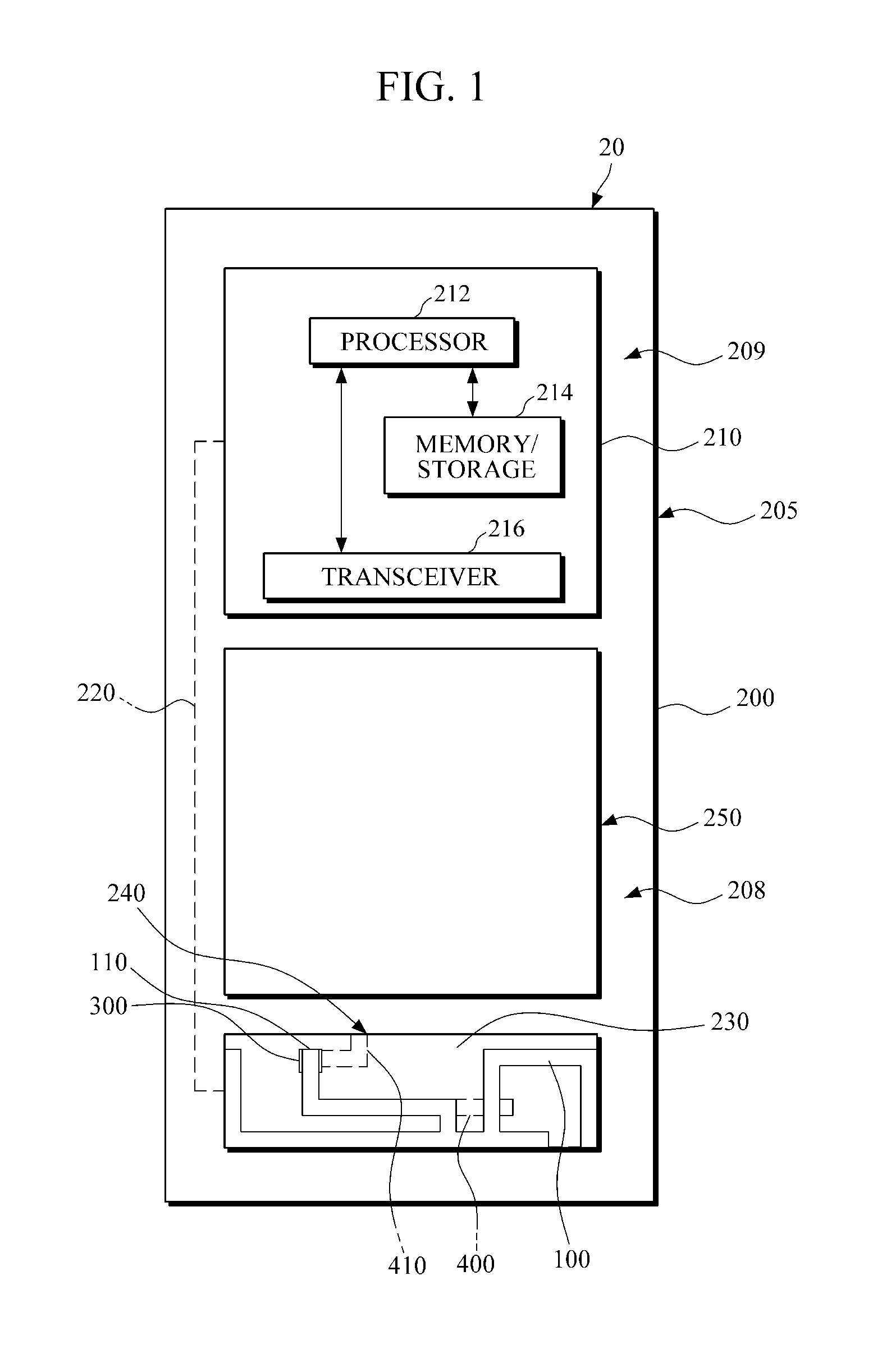
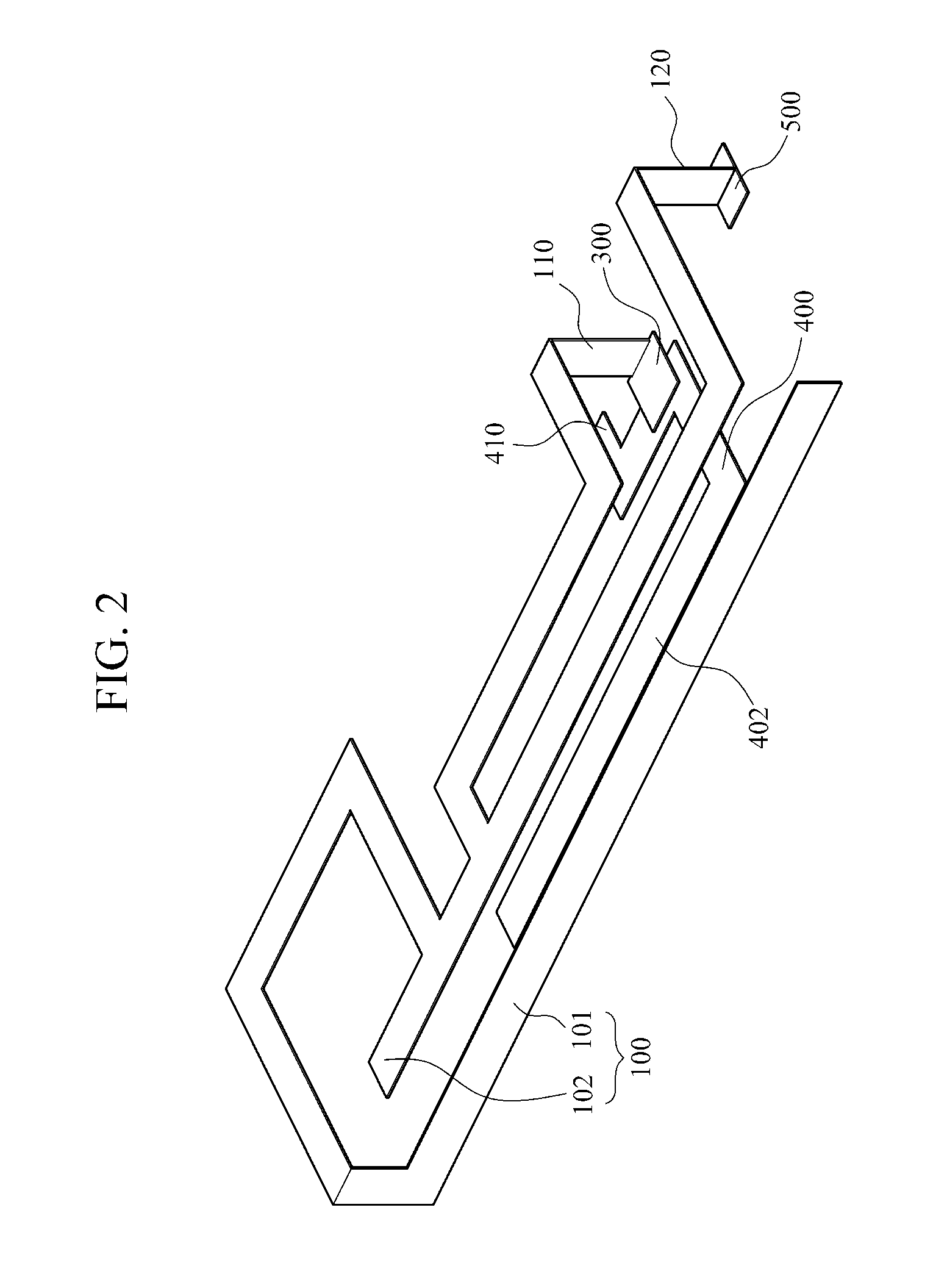
The present invention provides apparatuses and methods for wireless communication by a mobile terminal apparatus, such as a handheld or tablet computer, with an indirect feeding sub antenna to support a desired frequency band. The invention allows for the addition of a second frequency band or bands through feeding a sub antenna indirectly through coupling with a main antenna to produce an additional resonance. The invention also allows for the selective feeding of signals at one or more frequency bands directly or indirectly through a sub antenna. The technical effects of the invention include a wider frequency range support and improved wireless communication performance by a mobile terminal apparatus.

Problems solved by technology

Known first-generation mobile communication terminals may have stud type antennas that protrude out of their housings, the stud type antennas may be easily broken and limiting the design of the terminal.
However, such method may have difficulty in acquiring a wide receiving bandwidth.

Method used


Image

  • Mobile terminal apparatus and method for performing wireless communication using an indirect feeding antenna
  • Mobile terminal apparatus and method for performing wireless communication using an indirect feeding antenna
  • Mobile terminal apparatus and method for performing wireless communication using an indirect feeding antenna

Examples


Embodiment Construction

[0032]The invention is described more fully hereinafter with reference to the accompanying drawings, in which exemplary embodiments of the invention are shown. This invention may, however, be embodied in many different forms and should not be construed as limited to the exemplary embodiments set forth herein. Rather, these exemplary embodiments are provided so that this disclosure is thorough, and will fully convey the scope of the invention to those skilled in the art. Also, descriptions of well-known functions and constructions may be omitted for increased clarity and conciseness.

[0033]It will be understood that when an element is referred to as being “connected to” or “coupled to” another element, it may be directly connected or coupled to the other element or it may be indirectly connected or coupled to another element, or intervening elements may be present.

[0034]FIG. 1 is a plan view of a mobile terminal apparatus with an indirect feeding antenna according to exemplary embodim...


PUM

PropertyMeasurementUnit
Timeaaaaaaaaaa
Frequencyaaaaaaaaaa
Frequencyaaaaaaaaaa

Abstract

A mobile terminal apparatus and method for performing wireless communication, including a main antenna to transmit or receive signals at one or more first frequency bands, a sub antenna to transmit or receive signals at least at one second frequency band, and a feeding pad connected to the main antenna to directly supply power or signals to the main antenna to transmit or receive signals at the one or more first frequency bands, the feeding pad being spaced apart from or disposed within a reference proximity to and electrically coupled to the sub antenna to indirectly supply power or signals to the sub antenna to transmit or receive signals in the at least one second frequency band.

Description

CROSS-REFERENCE TO RELATED APPLICATION[0001]This application claims the benefit under 35 U.S.C. §119(a) of Korean Patent Application No. 10-2012-0023172, filed on Mar. 7, 2012, the entire disclosure of which is incorporated herein by reference for all purposes.BACKGROUND[0002]1. Field[0003]Exemplary embodiments relate to mobile terminal apparatuses and methods for performing wireless communication using an indirect feeding antenna to additionally support a desired frequency band.[0004]2. Discussion of the Background[0005]Development of antenna technologies has contributed to development of small-size, slim mobile communication terminals.[0006]Known first-generation mobile communication terminals may have stud type antennas that protrude out of their housings, the stud type antennas may be easily broken and limiting the design of the terminal.[0007]However, recently, an antenna, sometimes called an “intenna,” that is installed in a housing to be invisible externally has been introduc...

Claims


Application Information

Patent Timeline
IPC IPC(8): H01Q19/00
CPCH01Q19/00H01Q1/243H01Q5/378Y10T29/49016H01Q9/42H01Q1/24H01Q1/46H01Q9/04
Inventor YOON, HEE-JUNE
Owner PANTECH CO LTD
Learn More