Broadband antenna

Inactive Publication Date: 2010-01-07
SONY ERICSSON MOBILE COMM AB
View PDF1 Cites 0 Cited by
  • Summary
  • Abstract
  • Description
  • Claims
  • Application Information

AI Technical Summary

Benefits of technology

[0007]One object of the present invention is to provide a broadband antenna having the capability of being us

Problems solved by technology

The big variety of frequency bands causes problems if one would like to use one mobile terminal device in different frequency bands.
However, the bandwidth is related to the volume of the antenna and it might therefore be difficult to get e

Method used


Image

  • Broadband antenna
  • Broadband antenna
  • Broadband antenna

Examples


Example

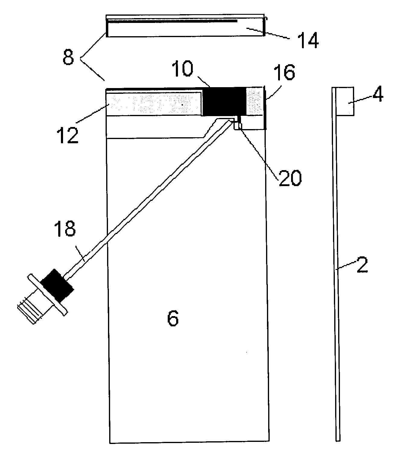
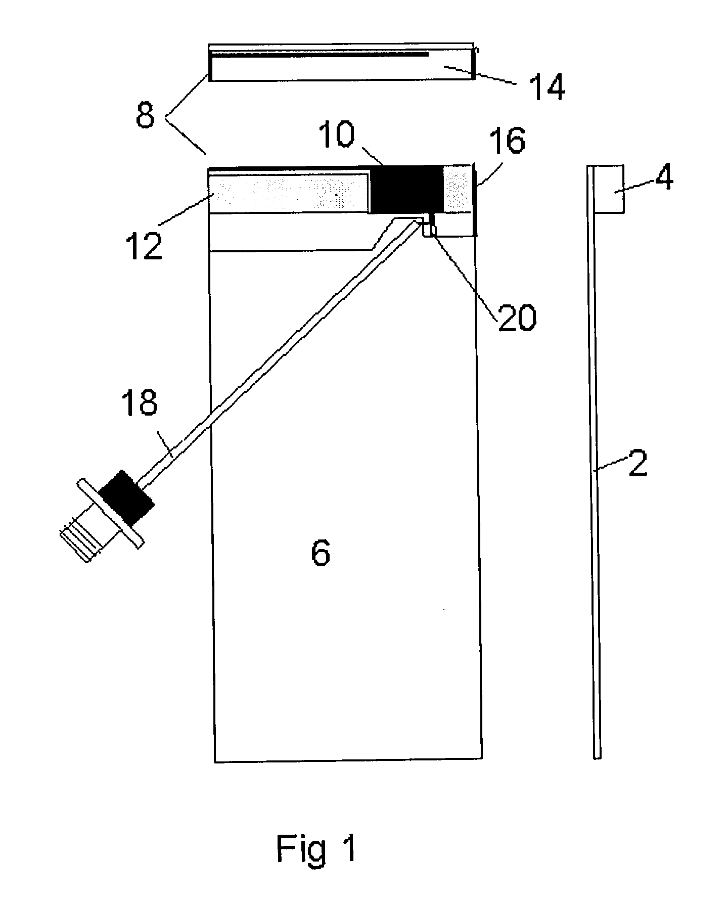
[0020]A broadband antenna capable of operating in six different frequency bands is depicted in FIG. 1. The broadband antenna is provided on an antenna support structure. The antenna support structure comprises two parts, namely a PCB (Printed Circuit Board) and rod-shaped part 4. The rod-shaped part is arranged on the upper short side of PCB. The size of the antenna support structure may vary, but is preferably kept small, due to the expectations on modern mobile terminal devices. In a preferred embodiment of the present invention the PCB 2 has a size of 45 mm by 100 mm. The rod-shaped part 4 is preferably 5 mm by 8 mm. Thus the antenna support structure only builds 5-6 mm in height depending on the thickness of the PCB 2. The antenna support structure is made of an isolating material, typically same kind of plastic. However, it is obvious to a person skilled in the art that other isolating materials may be used.

[0021]On the PCB 4 of the antenna support structure there is provided a...


PUM


Abstract

The present invention relates to a broadband antenna for at least six frequency bands provided on an isolating antenna support structure comprising. The antenna comprises a low band branch and a high band branch coupled to a substantially rectangular ground plane provided on a PCB. The coupling between the ground plane and the low band branch is a capacitive coupling and has a vertical distance of 3-7 mm there in between.

Description

TECHNICAL FIELD OF THE INVENTION[0001]The present invention relates to the field of broadband antennas for use with mobile terminal devices, such as mobile phones, PHS phones (Personal Handyphone System) and PDA equipment (Personal Digital Assistant) having communication functions. More particularly, the present invention relates to a broadband antenna for at least six frequency bands.DESCRIPTION OF RELATED ART[0002]Today there are a number of frequency bands that are used for different mobile terminal devices, such as mobile phones. The transmission and receiving of signals is made according to one or more wireless communication standards. For purpose of illustration, examples of a low frequency wireless communication band include the AMPS frequency band (Advanced Mobile Phone System) and the GSM low frequency band (Global System for Mobile communications). Examples of a high frequency wireless communication band include a GSM high frequency band, a PCS frequency band (Personal Com...

Claims


Application Information

Patent Timeline
IPC IPC(8): H01Q5/00H01Q1/00H01Q5/10
CPCH01Q1/38H01Q1/243
Inventor MOSER, MICHAEL
Owner SONY ERICSSON MOBILE COMM AB
Why Eureka
Try Eureka