

Collapsible tent frame with retractable eaves
- Summary
- Abstract
- Description
- Claims
- Application Information
AI Technical Summary
Benefits of technology
Problems solved by technology
Method used
Image

Examples
Embodiment Construction
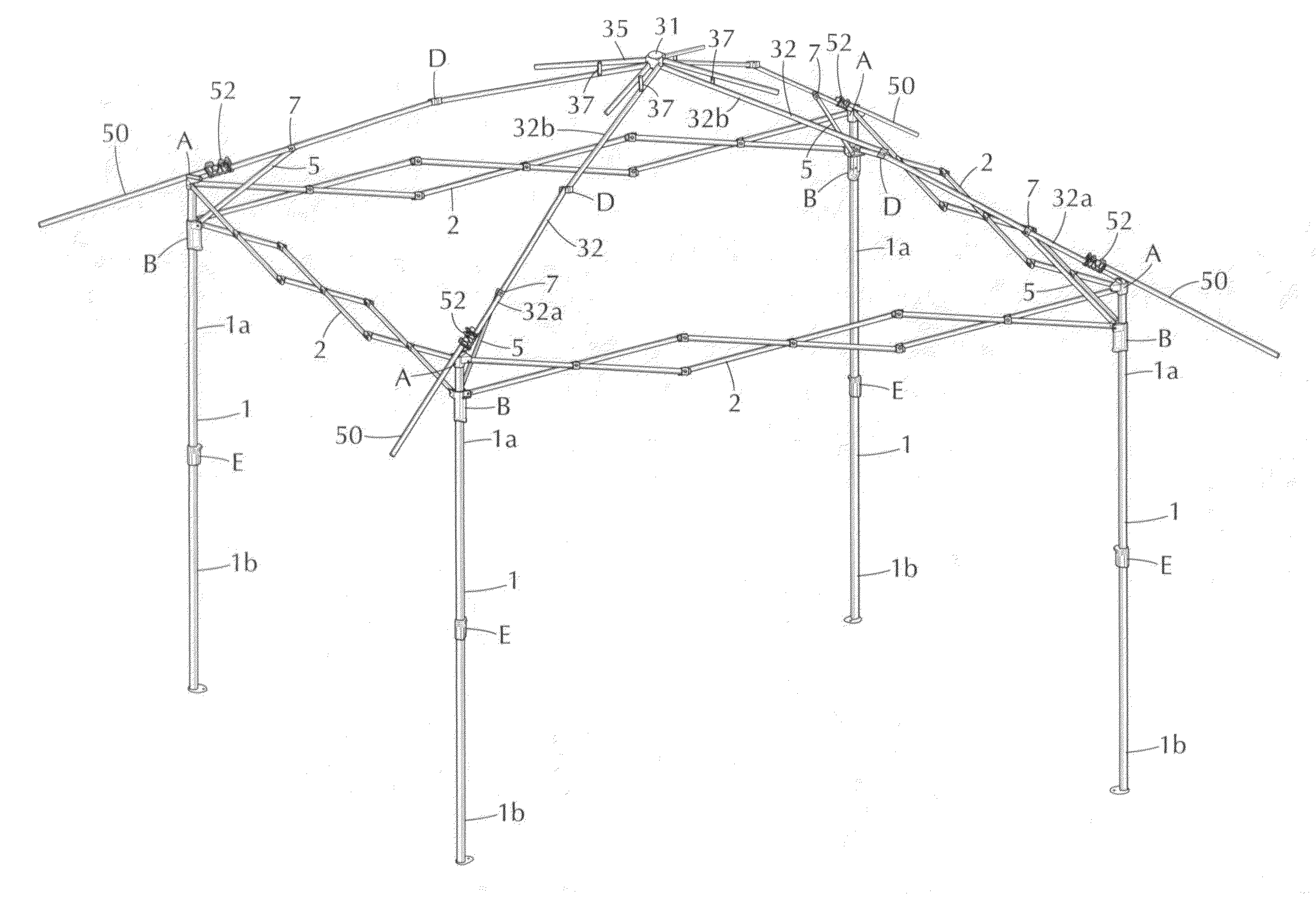
[0024]As shown in FIGS. 3-11, the collapsible tent frame of the present invention is a “one-touch” structure capable of opening and closing without additional assembly or disassembly. Referring to FIG. 3, the tent includes four vertically directed poles 1 constructed of an upper portion 1a and a lower portion 1b. The lower portion 1b is sized such that it slides in and out of the upper portion 1a, i.e., telescoping, and both upper and lower portions 1a, 1b can be “locked” at one or more height positions. Referring to FIGS. 3 and 8, the lower portion of the pole 1b includes a hole 103 which corresponds to a hole 104 of the upper portion 1a. A locking mechanism E is coupled to the pole 1 and comprises a spring 101 having an extension 105 which extends through the lower portion hole 103. The spring 101 is further secured within the lower portion 1b with a cap 109. A mount 110 having a pushbutton 107 is attached to the pole upper portion 1a and the button 107 is aligned with the upper p...
PUM
 Abstract
Description
Claims
Application Information