Seal device and sealing structure

Inactive Publication Date: 2007-06-28
DENSO CORP
View PDF3 Cites 2 Cited by
  • Summary
  • Abstract
  • Description
  • Claims
  • Application Information

AI Technical Summary

Benefits of technology

[0025] In still yet another aspect of the present disclosure, a sealing structure of the seal device is devised by having the first seal and second seal with accompanying support parts for accommodating a complex shape of the

Problems solved by technology

However, the sealing structure for sealing the air-conditioning unit in the above description has a p

Method used


Image

  • Seal device and sealing structure
  • Seal device and sealing structure
  • Seal device and sealing structure

Examples


Example

[0035] Embodiments of the present disclosure are described with reference to the drawings. Like parts have like numbers in each variation of the embodiments when the embodiment is described for more than one case.

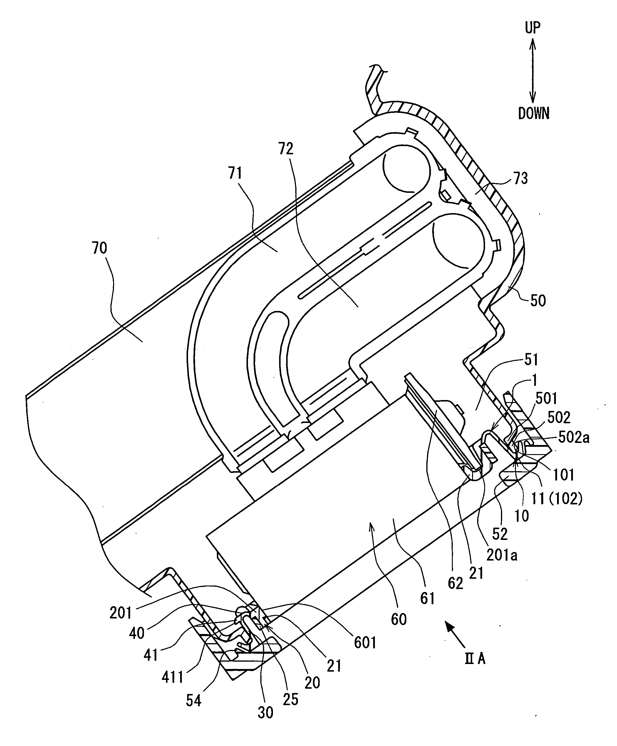
[0036]FIG. 1 shows a cross-sectional view of a sealing structure of a seal device 1 for sealing an air-conditioner in a vehicle in an embodiment of a present disclosure.

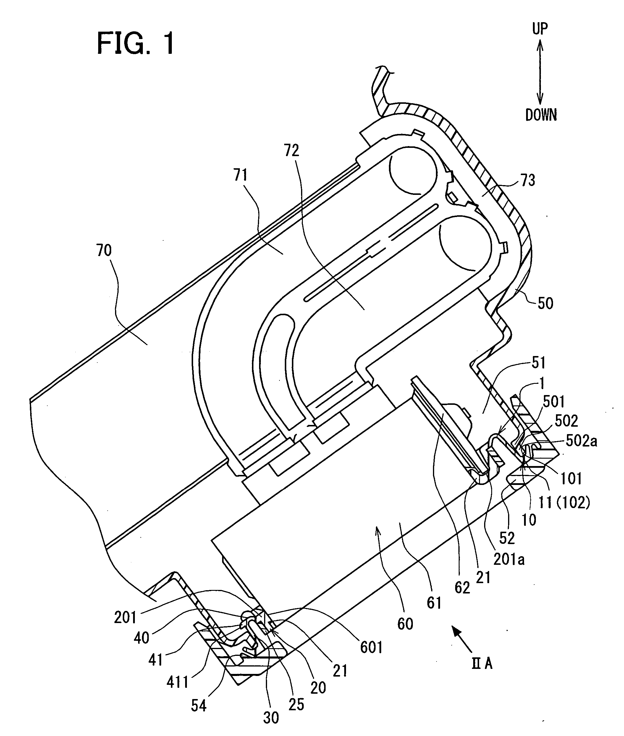
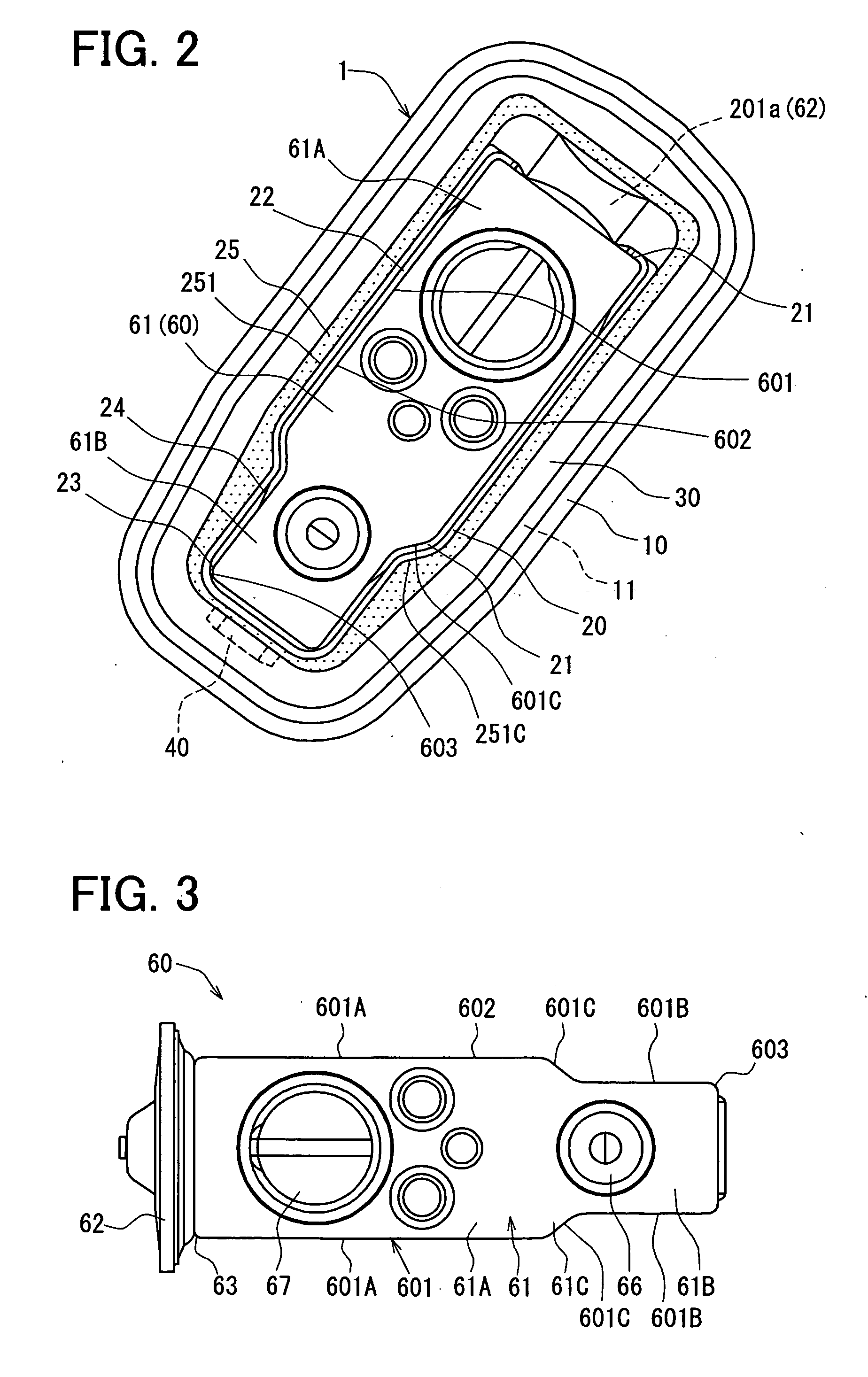
[0037]FIG. 2 shows an illustration of the sealing structure seen from a direction of an arrow A in FIG. 1. In FIG. 2, a case 50 and related parts are omitted from the figure for the clarity of engagement between an expansion valve 60 and the seal device 1. FIG. 3 shows a front view of the expansion valve 60 as a simple component. FIG. 4 shows a front view of the seal device 1 as a simple component. FIGS. 5A and 5B show cross-sectional views of the seal device 1 respectively taken along a line VB_VB and a line VC_VC in FIG. 4.

[0038] An air-conditioner unit of the present disclosure shown in FIG. 1 includes...


PUM


Abstract

A seal device has a for sealing a through hole in a partition includes a first seal for providing a first abutment portion that abuts against a periphery of the through hole in an entirety thereof, and a second seal for providing a second abutment portion that is made of an elastic material for abutting against an outer peripheral surface of a component disposed in the through hole. The first seal and the second seal are connected to cover an entire periphery of the through and the component, and a support member on the second seal has an inner surface shaped in a corresponding form of the component.

Description

CROSS REFERENCE TO RELATED APPLICATION [0001] This application is based on and claims the benefit of priority of Japanese Patent Application No. 2005-375669 filed on Dec. 27, 2005, and No. 2006-265520 filed on Sep. 28, 2006, the disclosure of which is incorporated herein by reference. FIELD OF THE INVENTION [0002] The present invention generally relates to a seal device for sealing a component. BACKGROUND OF THE INVENTION [0003] In recent years, a seal device for sealing a component in a through hole bored in a partition that divides two spaces is generally known as a sealing structure. More practically, the sealing structure seals a periphery of the through hole and an outer circumference of the component disposed therein. [0004] For example, Japanese patent document JP-A-2001-26213 discloses a vehicular air-conditioning unit with the through hole bored in a case that divides an inside air passage from an outer space. The through hole in the case has an expansion valve disposed the...

Claims


Application Information

Patent Timeline
IPC IPC(8): F25B41/06
CPCB60H2001/00635F25B41/062F25B2341/0683F25D23/006F25B41/335
Inventor ARAKI, YOSHINORINATSUME, TAKUYA
Owner DENSO CORP
Why Eureka
Try Eureka