Regulation for power supply mode transition to low-load operation

a technology of switching power converter and power supply mode, which is applied in the direction of electric variable regulation, process and machine control, instruments, etc., can solve the problems of discontinuity in the regulation of switching power converter, distortion of output voltage, and increased power consumption of portable electronic devices, so as to reduce unwanted output voltage ripple

Active Publication Date: 2013-09-12
DIALOG SEMICONDUCTOR INC
View PDF4 Cites 31 Cited by
  • Summary
  • Abstract
  • Description
  • Claims
  • Application Information

AI Technical Summary

Benefits of technology

[0008]Embodiments include a power regulation approach for transitioning from a first operating mode to a second operating mode by determining the operating conditions at the transition point using a point where the switch would have been turned on if operating under the first operating mode as a reference point to determine when to turn on the switch under the second operating mode. Using the reference point, the switching power converter determines a control period for regulating the switching period of the switch in a second operating mode. In one embodiment, the reference point coincides with the end of the off duration of the sw

Problems solved by technology

The efficiency demands placed on portable electronic devices create challenges for regulating power under changing load conditions.
These challenges include consuming nearly no power in standby mode, while delivering full power when the device is suddenly plugged-in for active power mode operation.
But, using multi-mode operation may introduce distortions in the output voltage caused by switching from one mode to another.
These distortions may result from discontinuity in the regulation of the switching power converter at the transition po

Method used


Image

  • Regulation for power supply mode transition to low-load operation
  • Regulation for power supply mode transition to low-load operation
  • Regulation for power supply mode transition to low-load operation

Examples


example switching

Power Converter Circuit

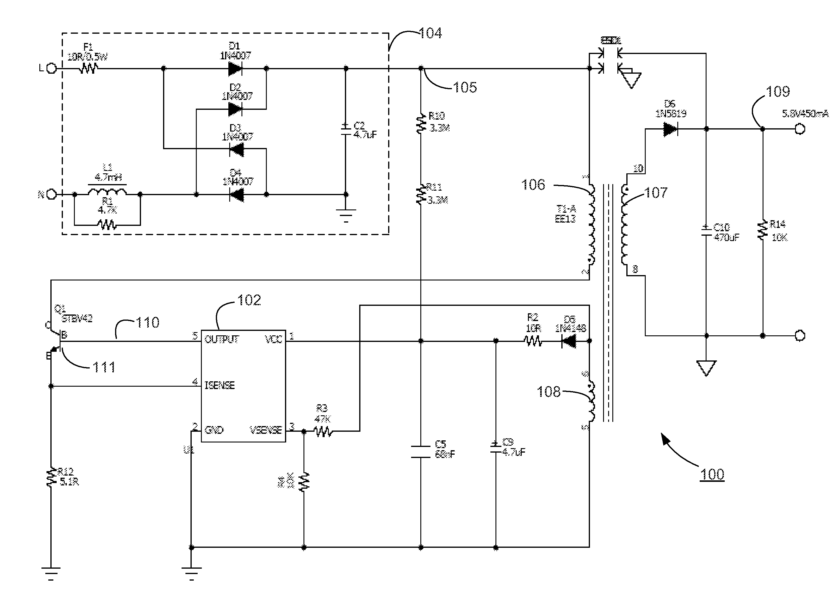
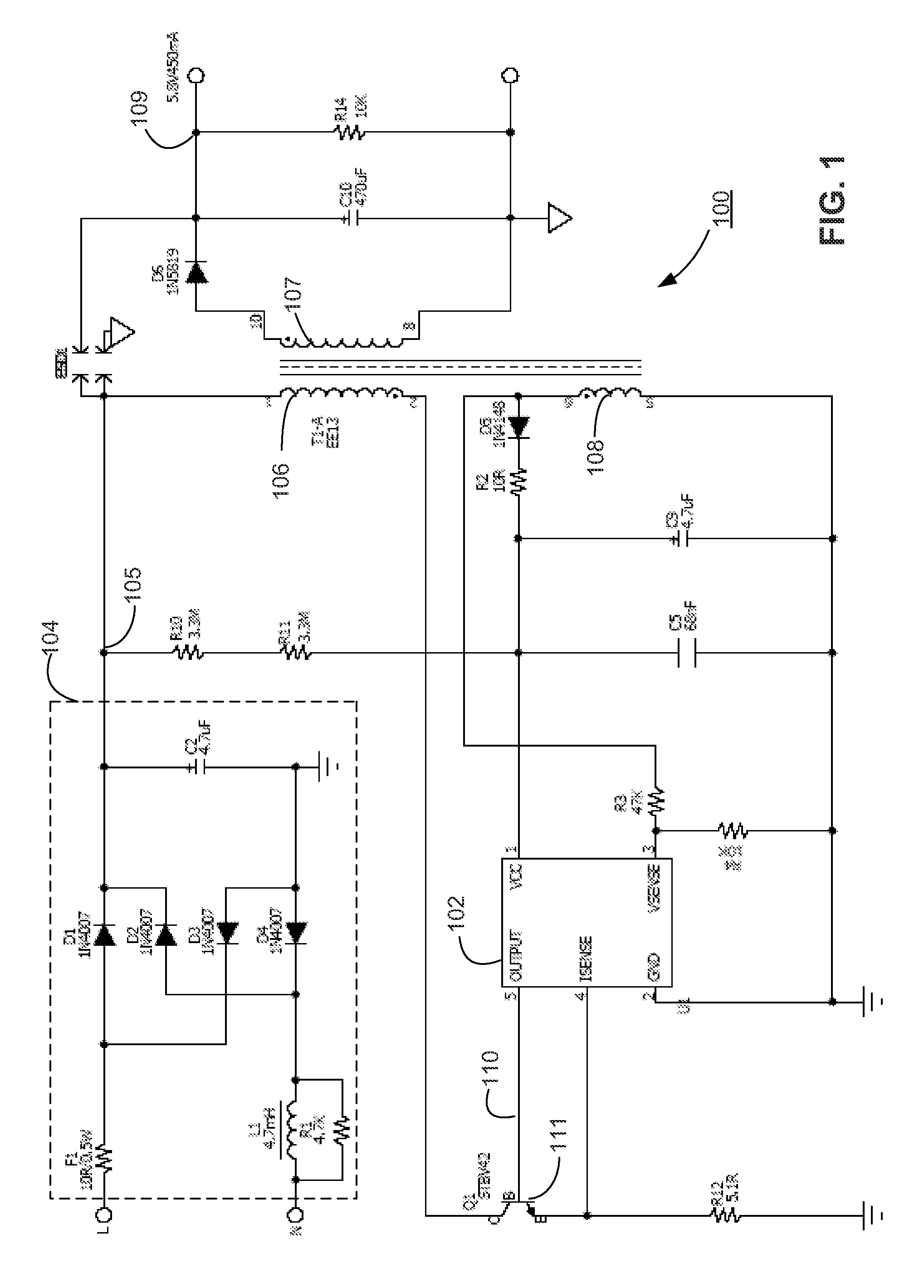
[0020]FIG. 1 is a circuit diagram illustrating a switching power converter 100, according to one embodiment. Switching power converter 100 is a primary-side feedback flyback converter, and includes three principal sections, i.e., a front end 104, power stage, and a secondary stage. The front end 104 is connected to an AC voltage source (not shown) at nodes L, N, and includes a bridge rectifier comprised of inductor L1, resistors R1, F1, diodes D1, D2, D3, D4, and capacitor C2. The rectified input line voltage at node 105 is input to the supply voltage pin Vcc (pin 1) of controller IC 102 via resistors R10 and R11. The line voltage at node 105 is also connected to the primary winding 106 of power transformer T1-A. Capacitor C5 removes high frequency noise from the rectified line voltage. The output of the front end section at node 105 is an unregulated DC input voltage.

[0021]The power stage includes power transformer T1-A, switch 111, and controller IC 102. Pow...


PUM


Abstract

A switching power converter includes a controller configured to transition from a first operating mode to a second operating mode by determining the operating conditions at the transition point between the operation modes. The controller uses a point where a switch included in the power converter would have been turned on if operating under the first operating mode as a reference point to determine when to turn on the switch under the second operating mode. Using the reference point, the switching power converter determines a control period for regulating the switching period of the switch in a second operating mode.

Description

CROSS REFERENCE TO RELATED APPLICATION[0001]This application claims priority under 35 U.S.C. §119(e) from co-pending U.S. Provisional Patent Application No. 61 / 608,031, filed on Mar. 7, 2012, which is incorporated by reference herein in its entirety.BACKGROUND[0002]1. Technical Field[0003]The present disclosure relates to controlling a switching power converter to reduce distortion of the output voltage waveform of the power converter when transitioning to low-load or no-load conditions.[0004]2. Description of the Related Arts[0005]The efficiency demands placed on portable electronic devices create challenges for regulating power under changing load conditions. These challenges include consuming nearly no power in standby mode, while delivering full power when the device is suddenly plugged-in for active power mode operation. And for many battery operated devices, these demands for power savings increasingly focus on low-load and no-load energy savings.[0006]To address these challen...

Claims


Application Information

Patent Timeline
IPC IPC(8): H02M3/335H02M1/00
CPCH02M3/33507H02M2001/0032Y02B70/16H02M1/0032Y02B70/10H02M1/12H02M3/28
Inventor YAN, LIANGKESTERSON, JOHN WILLIAMWANG, XIAOYAN
Owner DIALOG SEMICONDUCTOR INC
Why Eureka
Try Eureka