Dual tube frangible joint

a frangible joint and tube technology, applied in couplings, traffic signals, roads, etc., can solve the problems of unfavorable vehicle or mission operation,

Inactive Publication Date: 2013-09-12
ENSIGN BICKFORD AEROSPACE & DEFENSE
View PDF13 Cites 8 Cited by
  • Summary
  • Abstract
  • Description
  • Claims
  • Application Information

AI Technical Summary

Problems solved by technology

However, this arrangement may suffer from the drawback that sometimes the single, explosive cord fails to detonate as desired, thereby creating a risk that the two components may not separate as desired, potentially causing loss of vehicle or mission.
However, this arrangement can suffer from drawbacks such as cross propagation between the two explosive cords when one of the cords is ignited.
Other drawbacks include undesired sympathetic detonation of both explosive cords, secondary fracture of the structure, and duding failure modes.

Method used


Image

  • Dual tube frangible joint
  • Dual tube frangible joint
  • Dual tube frangible joint

Examples


Embodiment Construction

[0014]The present invention is more particularly described in the following description and examples that are intended to be illustrative only since numerous modifications and variations therein will be apparent to those skilled in the art. As used in the specification and in the claims, the singular form “a,”“an,” and “the” may include plural referents unless the context clearly dictates otherwise. Also, as used in the specification and in the claims, the term “comprising” may include the embodiments “consisting of” and “consisting essentially of” Furthermore, all ranges disclosed herein are inclusive of the endpoints and are independently combinable.

[0015]As used herein, approximating language may be applied to modify any quantitative representation that may vary without resulting in a change in the basic function to which it is related. Accordingly, a value modified by a term or terms, such as “about” and “substantially,” may not to be limited to the precise value specified, in s...


PUM

PropertyMeasurementUnit
flexibleaaaaaaaaaa
circumferenceaaaaaaaaaa
lengthaaaaaaaaaa

Abstract

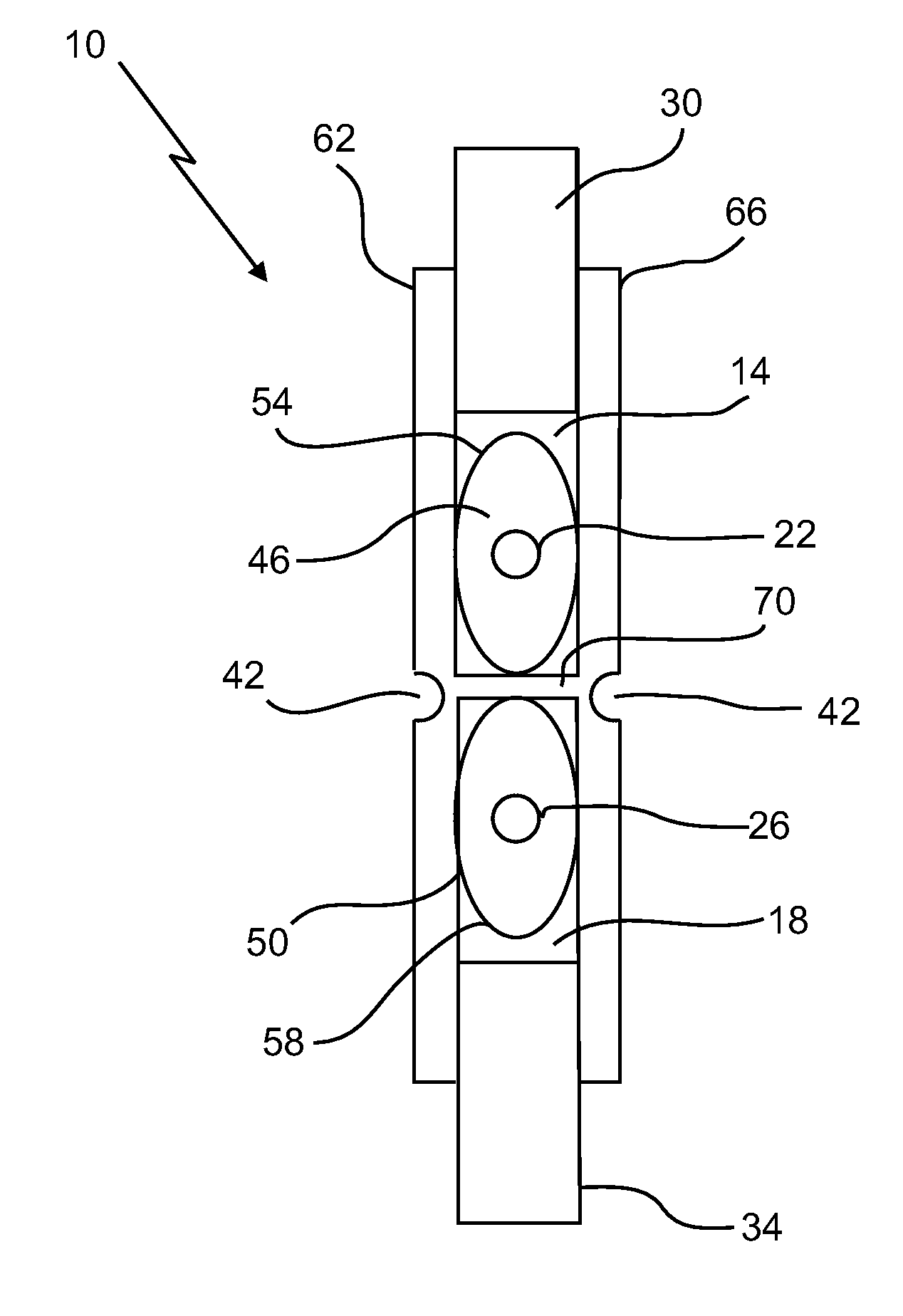
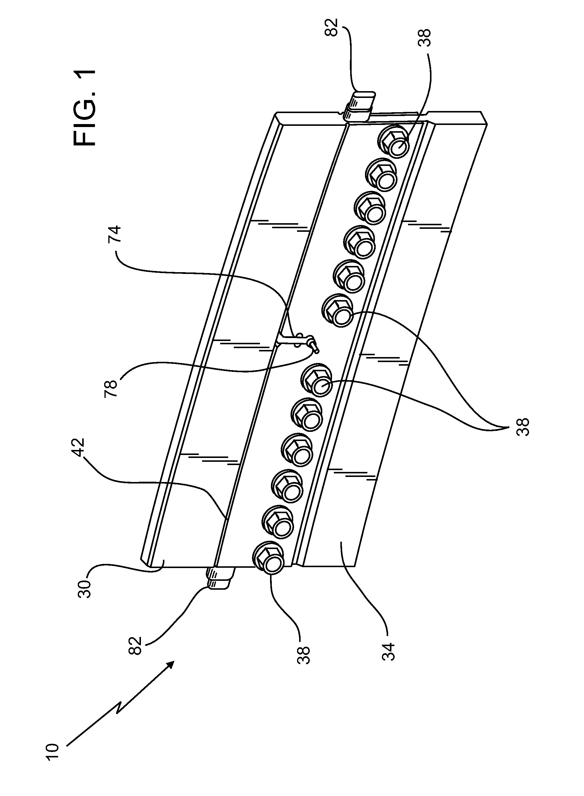
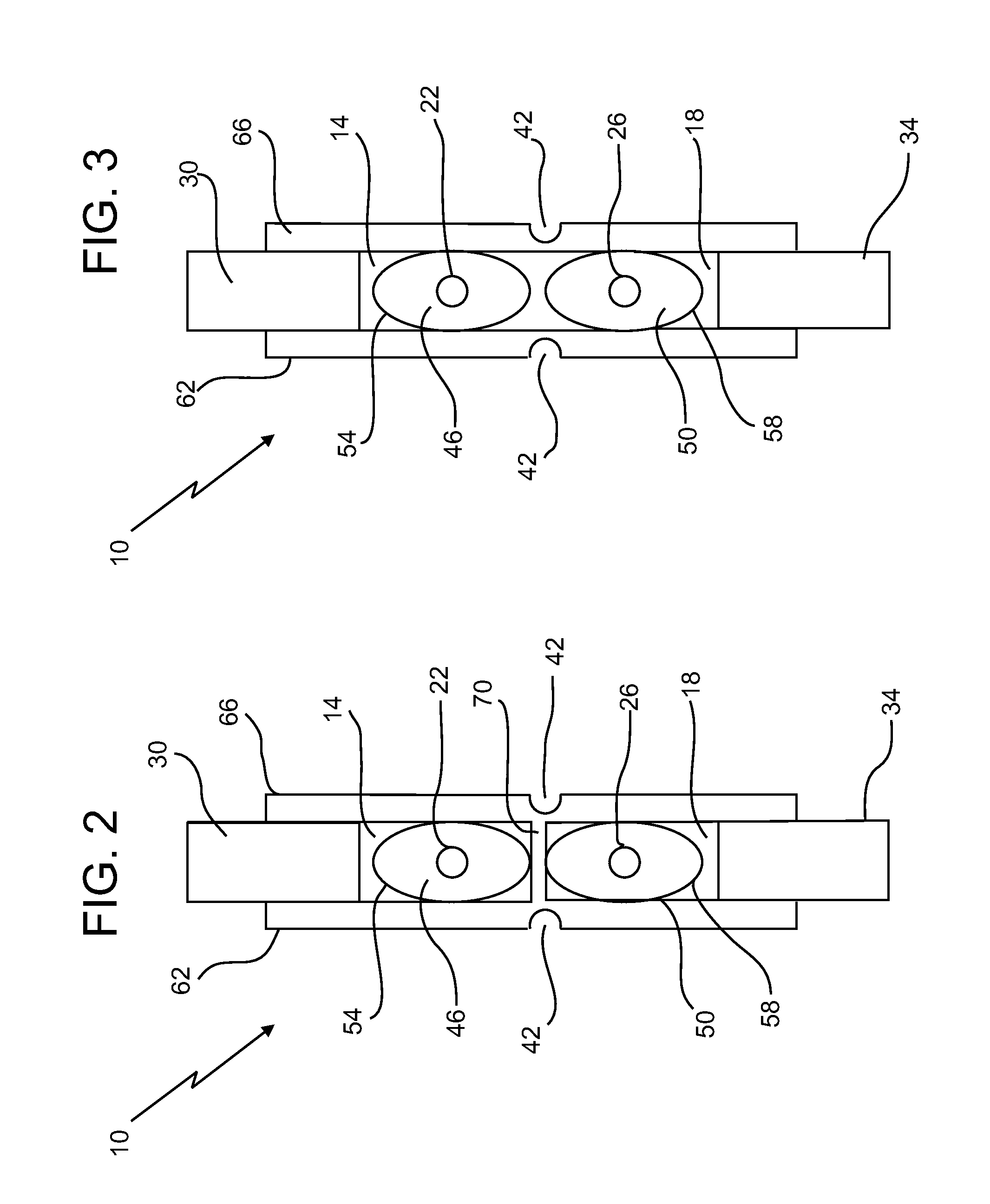
A frangible joint for separating a pair of components is provided. The frangible joint includes a first portion coupled one of the pair of components and a second portion coupled to the other of the pair of components. The first portion and the second portion are spaced apart by a gap. At least one plate is coupled between the first portion and the second portion across the gap. A first tube having a first explosive cord is disposed therein and a first pliable member arranged between the first explosive cord and the first tube, the first tube being disposed in the gap. A second tube having a second explosive cord is disposed therein and a second pliable member arranged between the second explosive cord and the second tube, the second tube being disposed in the gap adjacent the first tube.

Description

BACKGROUND OF THE INVENTION[0001]The present invention relates in general to frangible joint separation systems also known to as expanding tube separation, and in particular, to a dual tube frangible joint used to explosively separate two components in a reliable manner.[0002]It is known to utilize linear explosive frangible joints to explosively separate two components, such as that of a missile, satellite or other type of space or air travel vehicle during flight or operation (e.g., to separate two vehicle stages or to separate a payload from a launch vehicle). For example, it is known to utilize a single, elongated, flexible continuous explosive cord that comprises, e.g., a mild detonating fuse (“MDF”) that explodes upon detonation. The explosive cord may be encased in a silicone rubber or other pliable material that is surrounded by a stainless steel tube. This arrangement may be applied to a portion or all of the periphery or circumference of a joint, connection point or locati...

Claims


Application Information

Patent Timeline
Patent Type & Authority Applications(United States)
IPC IPC(8): B64G1/64C06C5/00
CPCB64G1/64Y10T403/11C06C5/00B64G1/645F16B2200/63
Inventor KACZYNSKI, GEOFFREY PAUL
Owner ENSIGN BICKFORD AEROSPACE & DEFENSE
Why Eureka
Try Eureka