Electronically controlled wheel lift system

a technology of electric control and wheel lift, which is applied in the direction of lifting devices, lifting frames, etc., can solve the problem of system level control that requires manual control, and achieve the effects of reducing time, reliable, and inexpensiv

Active Publication Date: 2013-09-19
GRAY MFG
View PDF16 Cites 52 Cited by
  • Summary
  • Abstract
  • Description
  • Claims
  • Application Information

AI Technical Summary

Benefits of technology

[0008]The vehicle lift system described herein can, in certain embodiments, provide one or more of the following benefits: (1) permit simultaneously lifting of both ends of a vehicle, (2) automatically maintain all lifts at substantially the same lifting height during lifting and lowering, (3) reduce time involved in operating lifts by allowing complete operation of all the lifts from one location, (4) employ inexpensive, safe, and reliable pneumatic power to lift the vehicle, and (5) permit pneumatic lifts to be used as support stands while both ends of the vehicle are raised.

Problems solved by technology

The stands are used in place of the lifting devices because of the added support provided by such stands, and because such stands do not allow inadvertent upward or downward shifting of the vehicle.
Further, the system requires manual level control during raising and lowering.

Method used


Image

  • Electronically controlled wheel lift system
  • Electronically controlled wheel lift system
  • Electronically controlled wheel lift system

Examples


Embodiment Construction

[0025]Detailed embodiments of the present invention are disclosed herein; however, it is to be understood that the disclosed embodiments are merely exemplary of the invention, which may be embodied in various forms. Therefore, specific structural and functional details disclosed herein are not to be interpreted as limiting, but merely as a basis for the claims and as a representative basis for teaching one skilled in the art to variously employ the present invention in virtually any appropriately detailed structure.

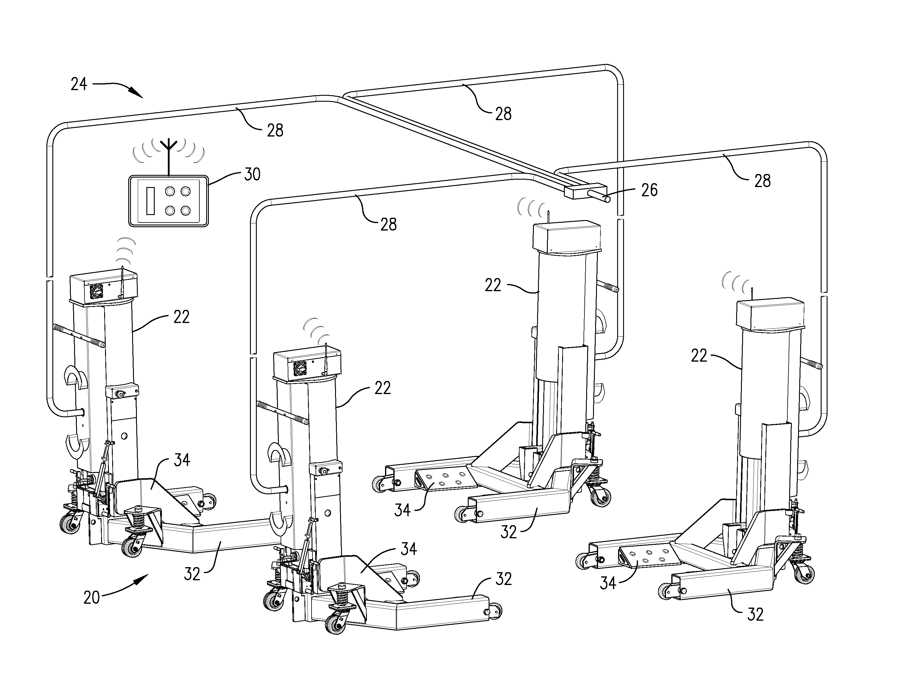
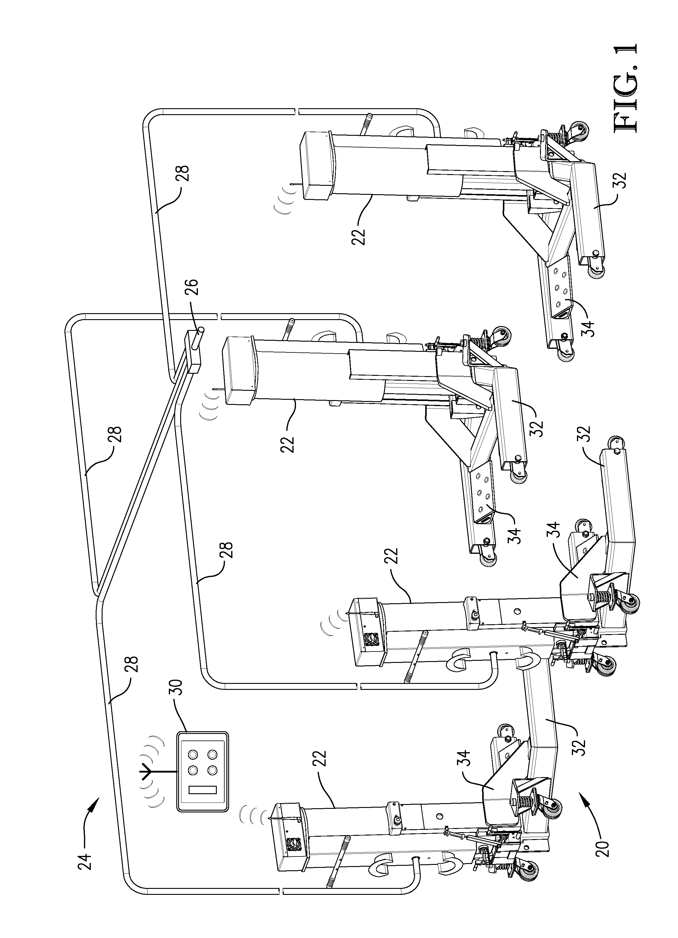
[0026]FIG. 1 illustrates a wheel-engaging pneumatic lift system 20 having four individual pneumatic lifts 22 that receive compressed air from an overhead air distribution system 24. Compressed air from an external source can be supplied to the overhead air distribution system 24 via a supply line 26. The air in the supply line 26 can be split among distribution lines 28, which each supply compressed air to a respective one of the pneumatic lifts 22. Although FIG. 1 depict...


PUM


Abstract

A wheel lift system capable of performing an electronically synchronized lift using two or more individual lifts. In one embodiment, the wheel lift system is pneumatically powered via an external source of compressed air, and the system is electronically controlled from a common control station / module. The common control station / module can include a moveable cart and / or a wireless handheld control module. In one embodiment, each lift of the wheel lift system is connected to a common movable cart and a user control interface is also connected, either physically or wirelessly, to the movable cart.

Description

CROSS-REFERENCE TO RELATED APPLICATIONS[0001]This application claims priority to U.S. Provisional Patent Application Ser. No. 61 / 612,670, filed Mar. 19, 2012, the entire disclosure which is incorporated herein by reference to the extent it does not contradict statements contained herein.BACKGROUND OF THE INVENTION[0002]1. Field of Invention[0003]The present invention relates generally to vehicle lifts and stands. More particularly, certain embodiments of the present invention relate to pneumatically powered vehicle lifts that employ dual mechanical locking mechanisms for enhanced safety when a vehicle is being held in a raised position.[0004]2. Discussion of the Prior Art[0005]The maintenance of vehicles such as cars and trucks frequently requires access to the underside of the vehicles in order to permit repair of parts such as transmissions, clutches, gearing, joints, brakes, and the like. In order to reach these areas of a vehicle, a worker typically employs one or more lifting d...

Claims


Application Information

Patent Timeline
Patent Type & Authority Applications(United States)
IPC IPC(8): B66F3/46
CPCB66F3/46
Inventor HELMICH, SETH A.
Owner GRAY MFG
Why Eureka
Try Eureka