

Directional coupler
a directional coupler and directional coupler technology, applied in coupling devices, waveguide type devices, basic electric elements, etc., can solve the problems of increasing the height dimension of the laminate block b>101/b>, the difficulty in optimizing the impedance characteristics of the output end derived from the first main line, and the size of the directional coupler must be increased, so as to reduce the number of dielectric layers and reduce the height of the directional coupler , the effect of stabil
- Summary
- Abstract
- Description
- Claims
- Application Information
AI Technical Summary
Benefits of technology
Problems solved by technology
Method used
Image

Examples
first preferred embodiment
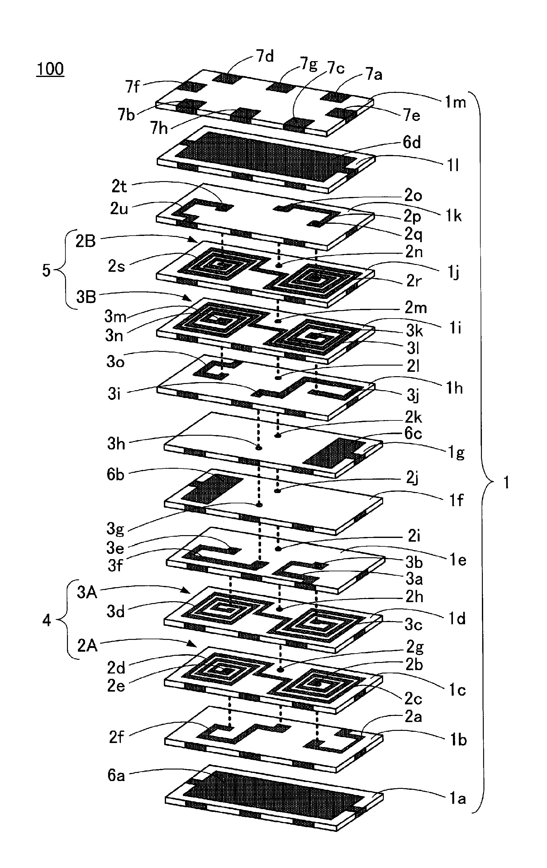
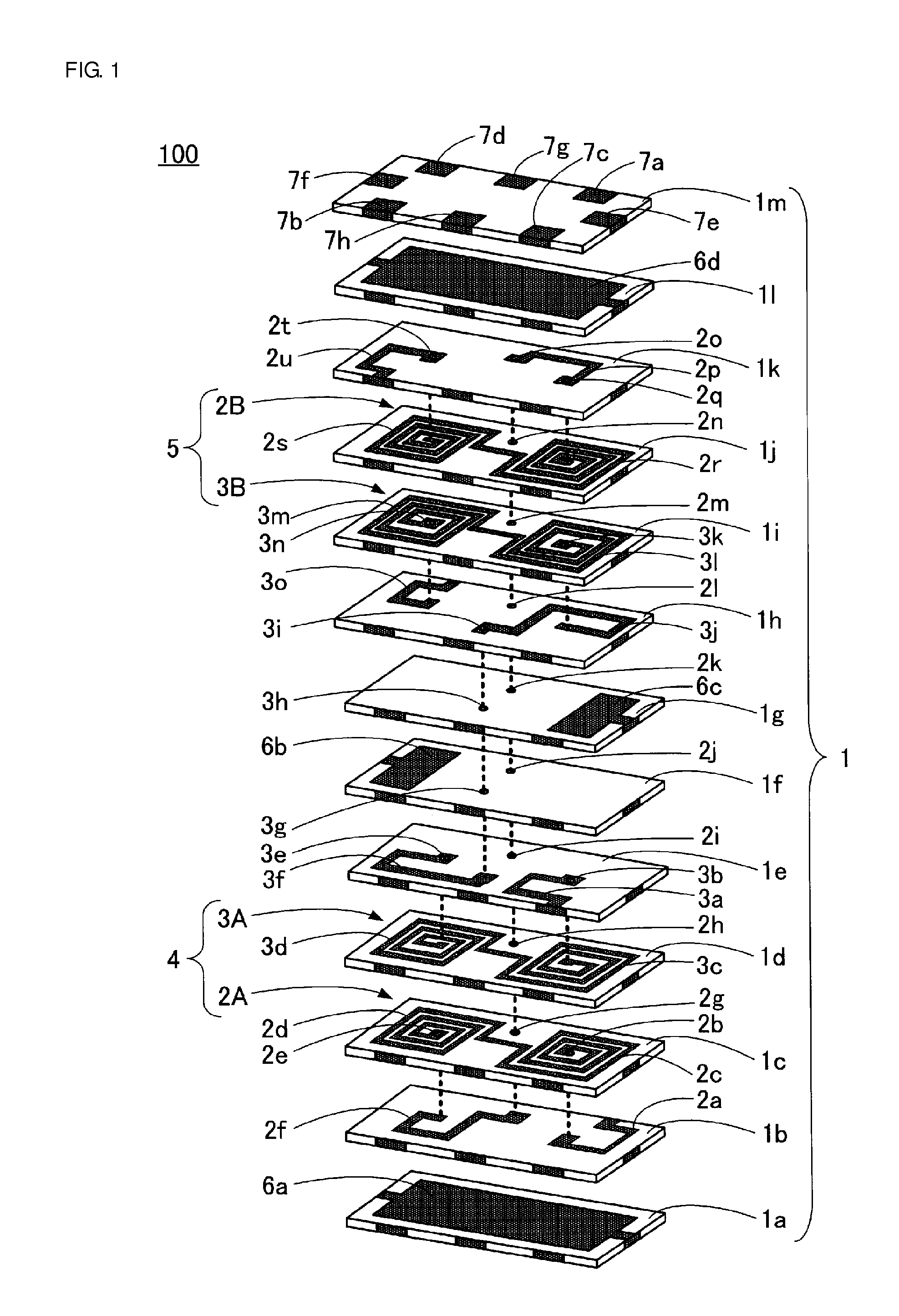
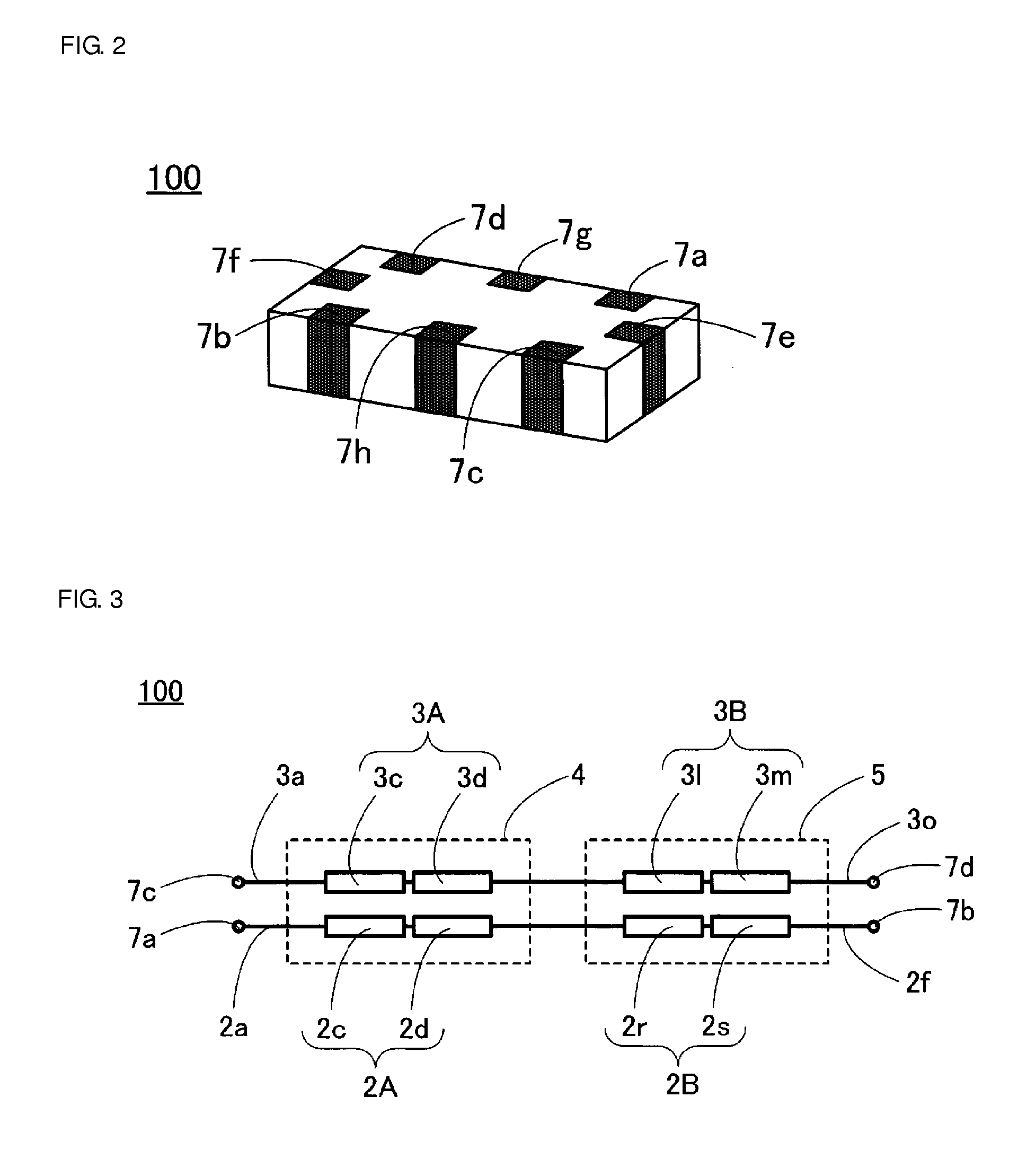
[0037]FIGS. 1 to 3 illustrate a directional coupler 100 according to a first preferred embodiment of the present invention. FIG. 1 is an exploded perspective view. FIG. 2 is a perspective view. FIG. 3 is an equivalent circuit diagram.
[0038]Firstly, as illustrated in FIG. 1, the directional coupler 100 according to the first preferred embodiment of the present invention includes a laminate block 1 including a plurality of laminated dielectric layers 1a to 1m.
[0039]Further, a connecting coil conductor 2a provided on a surface of the dielectric layer 1b, a via conductor 2b provided through the dielectric layer 1c, a divided coil conductor 2c provided on a surface of the dielectric layer 1c, a divided coil conductor 2d provided on the surface of the dielectric layer 1c, a via conductor 2e provided through the dielectric layer 1c, a connecting coil conductor 2f provided on the surface of the dielectric layer 1b, a via conductor 2g provided through the dielectric layer 1c, a via conducto...
second preferred embodiment
[0066]FIG. 4 illustrates a directional coupler 200 according to a second preferred embodiment of the present invention.
[0067]In the directional coupler 200, two divided ground conductors are provided on one dielectric layer, in place of the configuration of the directional coupler 100 according to the first preferred embodiment illustrated in FIG. 1, in which the divided ground conductor 6b and the divided ground conductor 6c are separately provided on two dielectric layers of the dielectric layer 1f and the dielectric layer 1g, respectively. That is, in the directional coupler 200, two divided ground conductors 16b and 16c are provided on a dielectric layer 11f in place of the dielectric layer 1f and the dielectric layer 1g. The dielectric layer 11f is also provided with a via conductor 12j and a via conductor 13g.
[0068]In the directional coupler 200, the dielectric layers 1a to 1e, the dielectric layer 11f, and the dielectric layers 1h to 1m are sequentially laminated to define a...
third preferred embodiment
[0070]FIG. 5 illustrates a directional coupler 300 according to a third preferred embodiment of the present invention.
[0071]In the directional coupler 300, two divided ground conductors are connected to each other by a connecting ground conductor, in place of the configuration of the directional coupler 200 according to the second preferred embodiment illustrated in FIG. 4, in which the two divided ground conductors 16b and 16c are arranged to be isolated from each other on the dielectric layer 11f. That is, in the directional coupler 300, two divided ground conductors 26b and 26c are provided on a dielectric layer 21f in place of the dielectric layer 11f, and are connected to each other by a connecting ground conductor 36. The dielectric layer 21f also includes a via conductor 22j and a via conductor 23g.
[0072]In the directional coupler 300, the dielectric layers 1a to 1e, the dielectric layer 21f, and the dielectric layers 1h to 1m are sequentially laminated to form a laminate bl...
PUM
 Abstract
Description
Claims
Application Information