
Electrical switch cabinet

a switch cabinet and switch technology, applied in the direction of electrical apparatus casings/cabinets/drawers, hinges, substation/switching arrangement casings, etc., can solve the problems of laborious and complicated handling of such large metal sheets

Inactive Publication Date: 2013-09-19
ABB (SCHWEIZ) AG
View PDF5 Cites 9 Cited by
  • Summary
  • Abstract
  • Description
  • Claims
  • Application Information

AI Technical Summary

Benefits of technology

This patent describes an electrical switch cabinet that is designed for low-voltage applications. The cabinet has a rear wall, side wall parts, and at least one movable front door. The side wall parts and rear wall are modular and connected rigidly together, and the front door can be guided by straps. The patent also describes a method for assembling the switch cabinet by connecting the walls and attaching the front door. The technical effects of this design are that the switch cabinet is stable and secure, and easy to assemble and install.

Problems solved by technology

Apart from the fact that this manner of production specifies large sheet-metal precursors so that the relevant switch cabinet can be produced virtually in one piece, handling of such large metal sheets can be complicated and laborious.

Method used

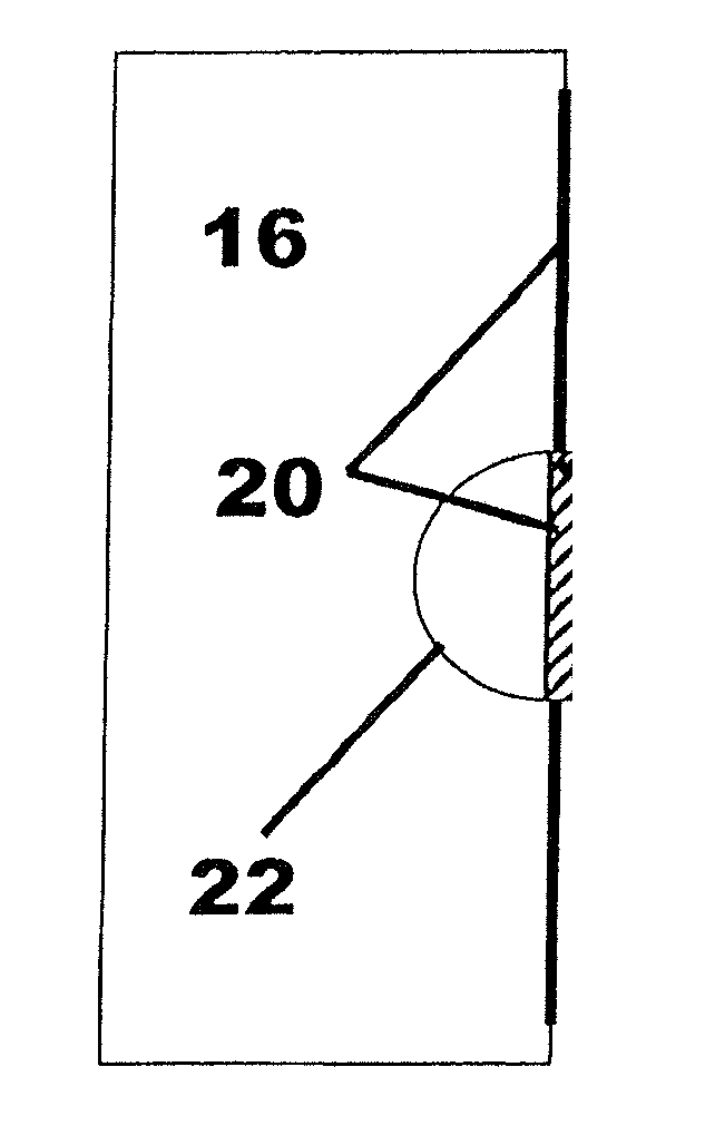
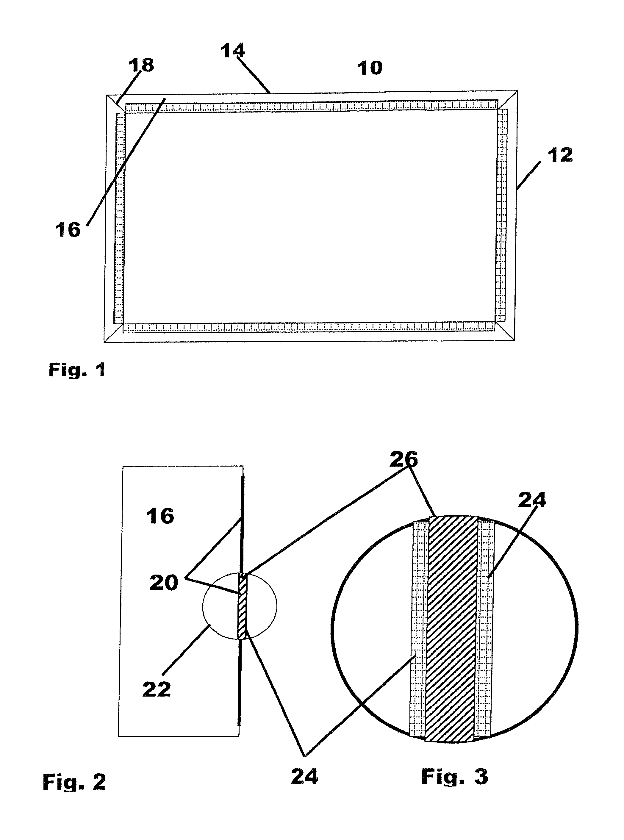

Image

  • Electrical switch cabinet
  • Electrical switch cabinet

Examples


Embodiment Construction

[0016]Exemplary embodiments of the present disclosure provide a switch cabinet of the type cited in the introductory part which is of simple design and is easy to handle.

[0017]The exemplary embodiments disclosed herein also provide for the side wall parts and the rear wall to be of modular design and to be rigidly connected to one another and for it to be possible for the at least one movable front door to be guided in grooves or by means of straps. “Of modular design” is intended to mean that the respective individual wall parts are punched-out and correspondingly bent, with the result that they can be connected to one another by means of integrally formed connecting edges and / or connecting surfaces.

[0018]In this way, sheet-metal modules of different sizes which are punched-out and bent can be produced for stock, and the respective wall parts for the relevant switch cabinet can be taken from this stock and combined to form the desired switch cabinet.

[0019]Exemplary embodiments of t...


PUM

PropertyMeasurementUnit
electric currentsaaaaaaaaaa
voltageaaaaaaaaaa
strengthaaaaaaaaaa

Abstract

An exemplary electrical switch cabinet for use in the low voltage range with voltages up to 500 V and electric currents up to 63 A, is constructed as a wall hung cabinet for surface or recessed mounting or as a standing cabinet, from a rear wall and side wall parts connected thereto. The cabinet can include at least one movable front door, and can be provided with internal fittings for the connection of switching devices arranged in the switch cabinet. The side wall parts and the rear wall are modularly configured and rigidly connected to one another, and the at least one movable front door can be guided in grooves through straps.

Description

RELATED APPLICATION(S)[0001]This application claims priority as a continuation application under 35 U.S.C. §120 to PCT / EP2011 / 005201, which was filed as an International Application on Oct. 17, 2011 designating the U.S., and which claims priority to German Application 10 2010 050 665.6 filed in Germany on Nov. 9, 2010. The content of each prior application is hereby incorporated by reference in its entirety.FIELD[0002]The disclosure relates to an electrical switch cabinet for use in the low-voltage range. The switch cabinet can be formed as a wall cabinet for surface or recessed mounting or as a stand-alone cabinet from a rear wall and from side wall parts which are connected to said rear wall. Alternatively, the switch cabinet can be formed with from at least one movable front door and provided with internal components for connecting switching devices which are arranged in the switch cabinet.BACKGROUND INFORMATION[0003]The rated current is known as the current which a plug connecto...

Claims


Application Information

Patent Timeline
Patent Type & Authority Applications(United States)
IPC IPC(8): H02B1/38H02B1/28
CPCH02B1/28Y10T29/24H02B1/38H02B1/30
Inventor BEIER, STEFAN
Owner ABB (SCHWEIZ) AG
Learn More