
Servers, Switches, and Systems with Virtual Interface to External Network Connecting Hardware and Integrated Networking Driver

a networking driver and server technology, applied in the field of systems, methods and computer programs for managing network traffic, can solve the problems of complex networking strategies to efficiently distribute packets in the network, difficult and inflexible management of multi-tier switches, and difficult implementation

Active Publication Date: 2013-09-19
PLURIBUS NETWORKS
View PDF4 Cites 53 Cited by
  • Summary
  • Abstract
  • Description
  • Claims
  • Application Information

AI Technical Summary

Benefits of technology

The patent describes a system for implementing a distributed switch layer fabric for networking devices. The system includes a switch module with ports for different types of networks, a server with a virtual driver for the switch module, and a switch controller. The server encapsulates packets in a different format and sends them to the switch module, which then transforms them back to their original format for transmission. The system allows for efficient switching of packets and maintains network policies. The technical effects of the patent include improved network performance and reliability.

Problems solved by technology

The proliferation of network devices has resulted in complex networking strategies to distribute packets in a network efficiently.
In some solutions, multitier switching devices are used to build the network, but these complex multitier solutions do not provide an efficient distribution of packets at the level 2, and the management of these multitier switches is difficult and inflexible.
The addition of virtual networks, that include virtual machines and other network devices, requires an efficient separation of traffic between the different virtual networks, which is difficult to implement in the multitier switching architecture.

Method used


Image

  • Servers, Switches, and Systems with Virtual Interface to External Network Connecting Hardware and Integrated Networking Driver
  • Servers, Switches, and Systems with Virtual Interface to External Network Connecting Hardware and Integrated Networking Driver
  • Servers, Switches, and Systems with Virtual Interface to External Network Connecting Hardware and Integrated Networking Driver

Examples


Embodiment Construction

[0047]The following embodiments describe systems, devices, methods, and computer programs for a distributed network device operating system (ndOS). It will be apparent, that the present embodiments may be practiced without some or all of these specific details. In other instances, well known process operations have not been described in detail in order not to unnecessarily obscure the present embodiments.

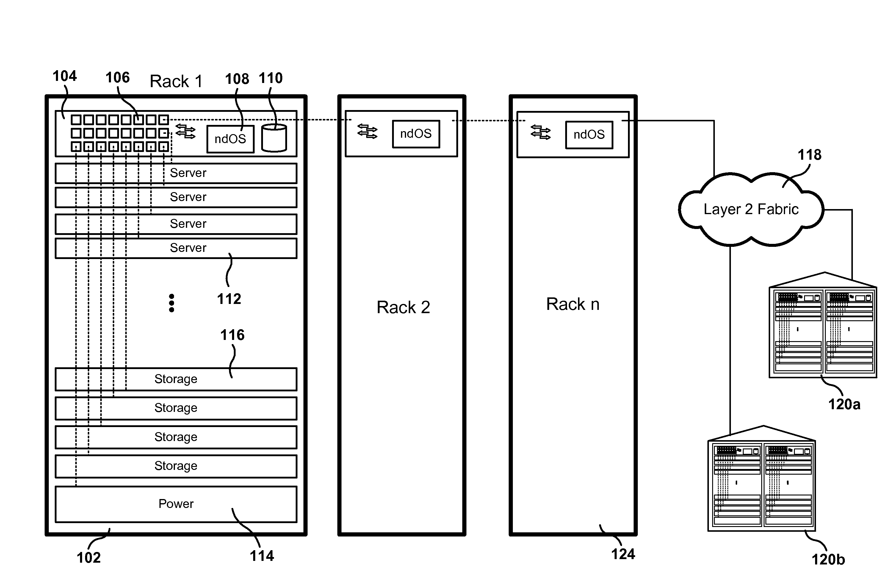
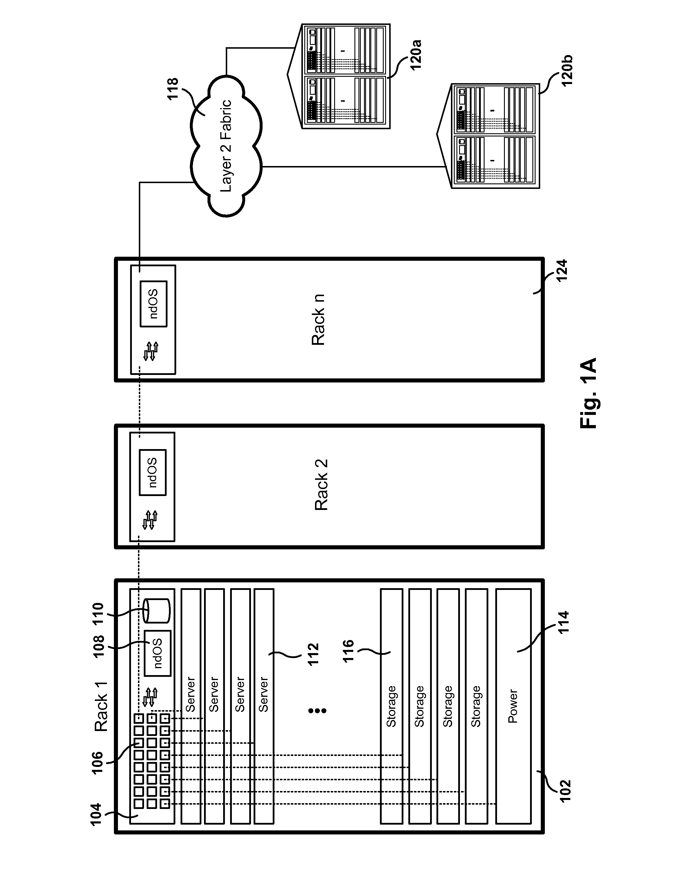
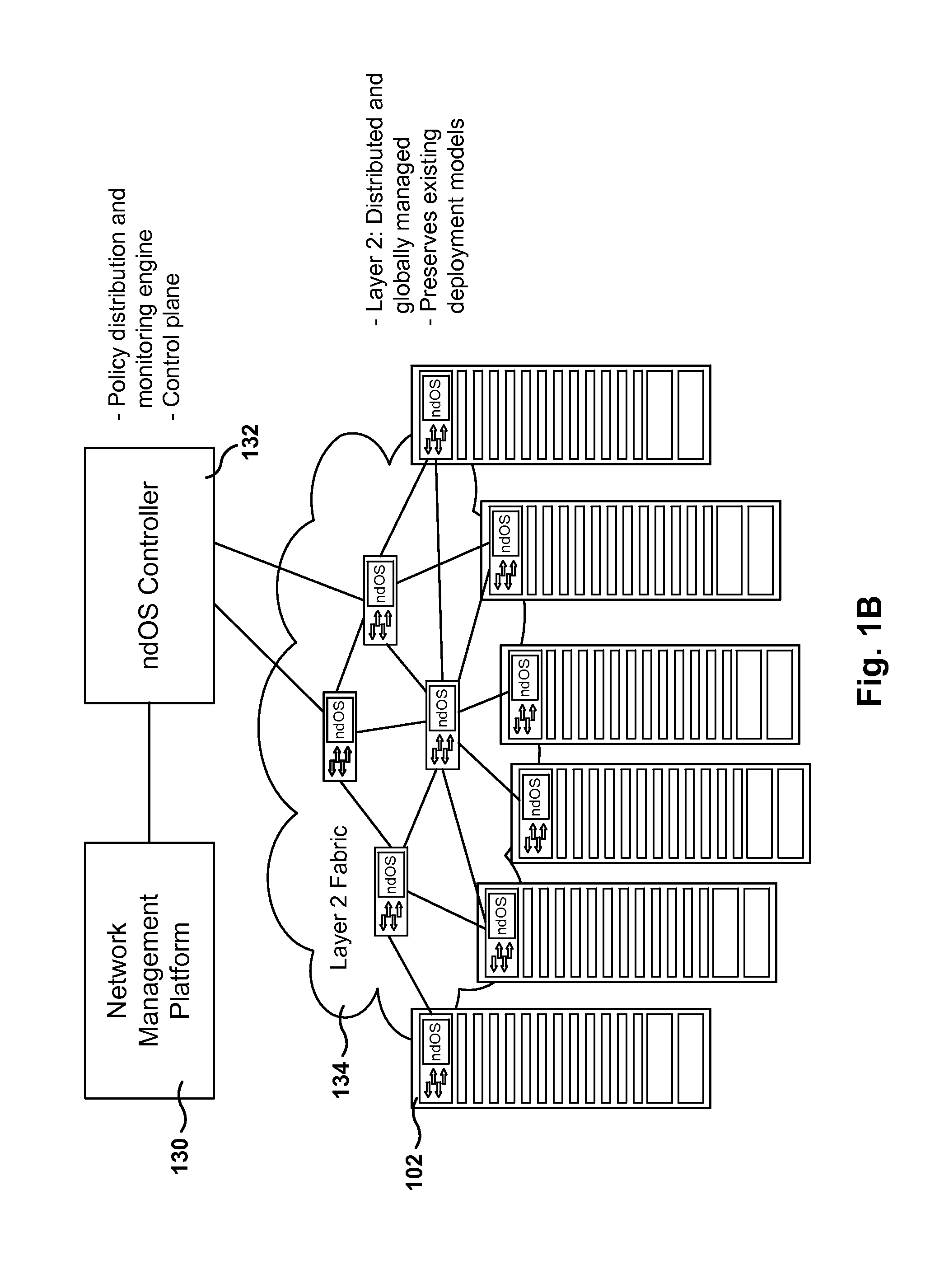
[0048]FIGS. 1A-1B illustrate the architecture of a distributed Network Device Operating System (ndOS), according to one embodiment. The network environment of FIG. 1A includes a rack 102 with a plurality of servers 112, storage devices 116, power supplies 114, etc. In addition, rack 102 includes a switch 104.

[0049]Switch 104 includes an instance of the ndOS, permanent storage 110, and a plurality of Ethernet ports 106 (more details regarding the components of switch 104 are given below with reference to FIGS. 5-7, 9A-9H, and others). The ndOS is a distributed network device operatin...


PUM


Abstract

Methods, systems, and computer programs are presented for networking communications. One method includes an operation for receiving a packet in a first format by a virtual driver providing a communications interface of a first type (CI1), the first format being for CI1. Further, the method includes an operation for encapsulating the packet in a second format by a processor, the second format being for a communications interface of a second type (CI2) different from CI1. In addition, the method includes an operation for sending the encapsulated packet in the second format to a switch module. The switch module includes a switch fabric, one or more CI1 ports, and one or more CI2 ports, and the switch module transforms the packet back to the first format to send the packet in the first format to a CI1 network via one of the CI1 ports in the switch module.

Description

CLAIM OF PRIORITY[0001]This application is a Continuation In-Part Application and claims priority from U.S. application Ser. No. 13 / 313,837, entitled “DISTRIBUTED OPERATING SYSTEM FOR A LAYER 2 FABRIC,” and filed on Dec. 7, 2011, which claims benefit under 35 U.S.C. §119(e) to U.S. Provisional Application Ser. No. 61 / 420,526, entitled “DISTRIBUTED OPERATING SYSTEM FOR A LAYER 2 FABRIC,” filed on Dec. 7, 2010;[0002]U.S. application Ser. No. 13 / 478,179, entitled “METHOD AND SYSTEM FOR PROCESSING PACKETS IN A NETWORK DEVICE,” and filed on May 23, 2012, which claims benefit under 35 U.S.C. §119(e) to U.S. Provisional Application Ser. No. 61 / 489,085 entitled “LOW LATENCY NETWORK FABRIC,” filed on May 23, 2011;[0003]U.S. application Ser. No. 13 / 100,125, entitled “SWITCH FABRIC FOR NETWORK DEVICES,” and filed on May 3, 2011, which claims benefit under 35 U.S.C. §119(e) to U.S. Provisional Application Ser. No. 61 / 330,758, entitled “VIRTUAL NETWORKS,” filed on May 3, 2010, and U.S. Provision...

Claims


Application Information

Patent Timeline
IPC IPC(8): H04L12/70
CPCH04L49/25H04L49/35H04L49/65H04L69/321H04L49/254H04L63/20H04L41/0893H04L41/0895H04L41/342H04L41/0894H04L47/10H04L63/0263H04L41/0806H04L49/70
Inventor TRIPATHI, SUNAYDROST, ROBERT JAMESYANG, CHIH-KONG KEN
Owner PLURIBUS NETWORKS
Learn More