Detection Process for a Receiver of a Wireless MIMO Communication System

a wireless mimo communication and receiver technology, applied in the field of wireless communication, can solve the problems of np-hard problem, performance loss compared to the ml detector, and many implementation problems, and achieve the effect of limiting the complexity of the algorithm and near-ml performan

Inactive Publication Date: 2013-09-19
ST ERICSSON SA
View PDF24 Cites 8 Cited by
  • Summary
  • Abstract
  • Description
  • Claims
  • Application Information

AI Technical Summary

Benefits of technology

[0022]It is an object of the present invention to carry out a process of detection for a MIMO receiver which achieves near-ML performance while limiting complexity of the algorithm.

Problems solved by technology

The SD principle has been introduced and leads to numerous implementation problems.
In particular, it is a NP-hard problem.
However, this solution makes the detector to be sub-optimal since its leads to a performance loss compared to the ML detector.
However, although a neighbourhood sourly remains the one and only solution that achieves ML performance, it may lead to the use of a large size neighbourhood scan which would correspond to a dramatic increase of the computational complexity.
A computational complexity reduction through adjacent-channel information re-use is not possible, even if the channel may be considered as constant over a certain block code size.
However, the overall performance shows to be still far from the ideal ML-detection and it is therefore desirable to improve such preprocessing by an additional processing phase which significantly increases the performance of the detection while limiting the processing resources being required with the classical K-Best.

Method used


Image

  • Detection Process for a Receiver of a Wireless MIMO Communication System
  • Detection Process for a Receiver of a Wireless MIMO Communication System
  • Detection Process for a Receiver of a Wireless MIMO Communication System

Examples


Embodiment Construction

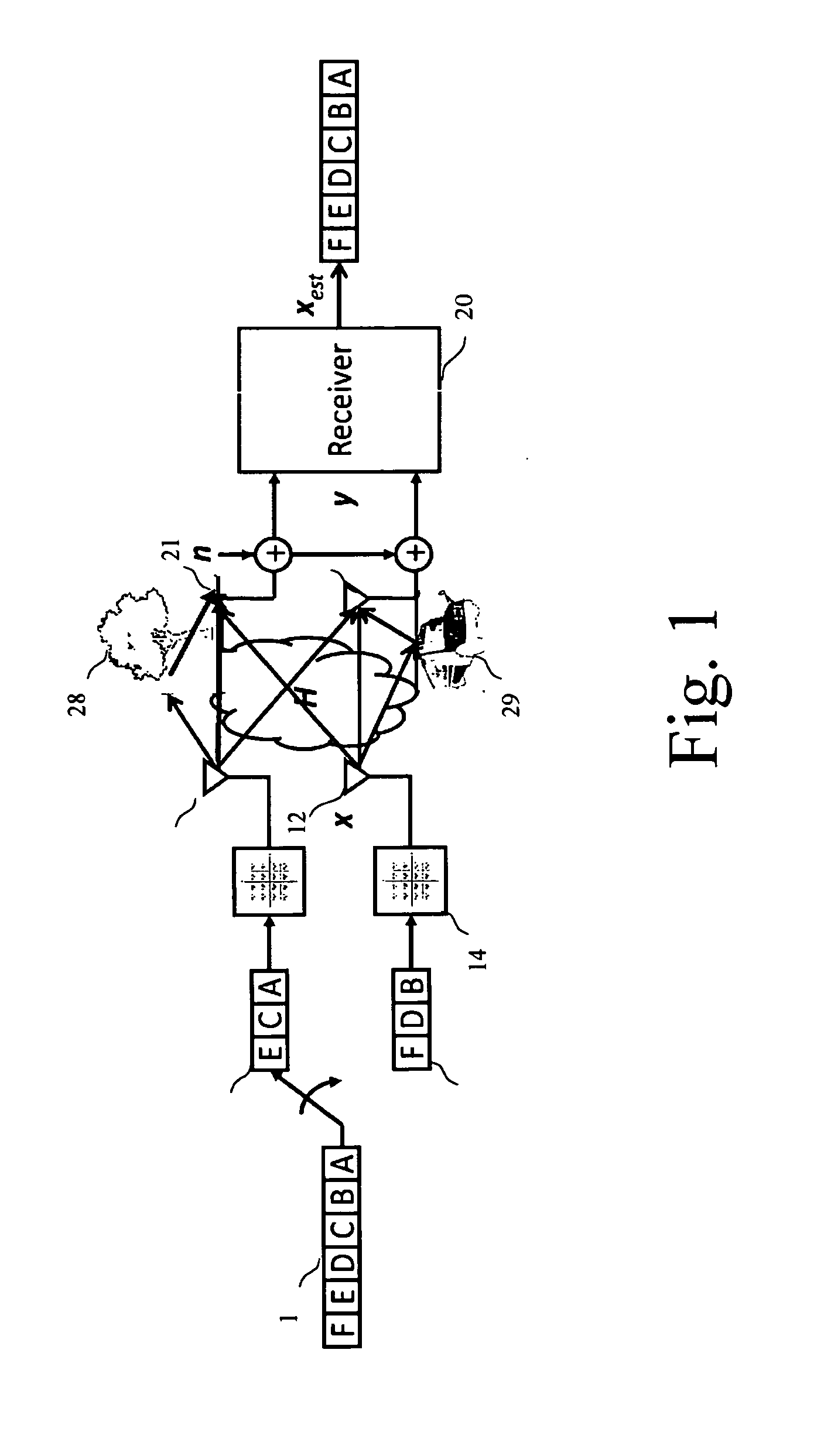
[0059]There will now be described one particularly embodiment of a process which is adapted to carry out a receiver for a MIMO wireless communication system, such as a Orthogonal Frequency Division Multiplex (OFDM).

[0060]In order to clarify the description of the process (II), some theoretical considerations will be introduced first (I).

I. Theoretical Considerations

[0061]The conventional and basic Sphere Detector is based on the Equation (1)—recalled above—which is centered on the received signal y.

[0062]In the case of a depth-first search algorithm, the Babai point is defined as the first solution that is given by the algorithm. For such conventional system, the induced Babai point is implicitly a Zero Forcing-Successive Interference Canceller (ZF-SIC) and, in the case of a Fixed Neighborhood Size Algorithm (FNSA), this definition is extended and is considered as the solution that would be directly reached, with no neighborhood study.

[0063]In opposition with the above mentioned Bab...


PUM


Abstract

A detection process for a receiver of a wireless communication system based on Multiple-In-Multiple-Out antennas, the process involving: —a preprocessing which only depends on the channel H, said preprocessing involving: —A QRD decomposition (61) for the purpose of decomposing said channel H into two Q and R matrices, with QHQ=I and R being upper triangular; —a lattice reduction (62) for the purpose of generating (formula AA, formula BB) and a permutation matrix T; —a loading phase (63, 64, 65) comprising a linear LRA-Minimum-Mean-Square-Error equalization applied on said symbols y in accordance with the result of said lattice reduction for the purpose of generating a value (formula CC). The process is characterized by the fact that it further involves the steps of: —Performing a neighborhood search with a search center being equal to the result (formula CC) of said lattice reduction; —Determining the -BKest symbols in accordance with a Partial Euclidean Distance (PED) defined in accordance with the following formula (formula DD)—detecting each layer and with the result of said detection performing an update of the search center so as to perform detection of the next layer; —multiplying the estimated value (formula EE) by said matrix T plus quantizing it onto the original constellation so as to generate the estimated value (formula FF).

Description

TECHNICAL FIELD[0001]The invention relates to the field of wireless communication and more particularly to a process for performing near-ML detection in a receiver of a wireless MIMO communication system.BACKGROUND ART[0002]Wireless communications based on multiple antennas is a very promising technique which is subject to extensive investigations so as to take into advantage of the significant increase of data rate which may be obtained by such technique.[0003]FIG. 1 illustrates a basic 2×2 multiple-Input Multiple Output (MIMO) spatial multiplexing communication between an emitter 10 and a receiver 20, and the processing of a single data flow—represented by reference 1—which is divided into two distinctive data streams 2 and 3 by means of a multiplexer 15 and each subflows are then being processed by a respective modulator and RF circuit (resp. 13 and 14) before being conveyed to two transmit antennas 11 and 12.[0004]On the receiver side, two antennas 21 and 22 provides two RF sign...

Claims


Application Information

Patent Timeline
Patent Type & Authority Applications(United States)
IPC IPC(8): H04B7/08
CPCH04B7/0854H04L25/0246H04B7/0885H04L2025/03426H04L25/03242
Inventor AUBERT, SEBASTIEN
Owner ST ERICSSON SA
Why Eureka
Try Eureka