Method and apparatus for transferring article layers between adjacent modules

a technology for transferring article layers and adjacent modules, which is applied in the direction of de-stacking articles, mechanical conveyors, packaging, etc., can solve the problems of individual articles falling, affecting the safety of the article, and the risk of toppling or becoming dislodged the highest, and the risk of falling over or becoming dislodged the greates

Active Publication Date: 2013-09-19
KRONES AG
View PDF19 Cites 10 Cited by
  • Summary
  • Abstract
  • Description
  • Claims
  • Application Information

AI Technical Summary

Benefits of technology

[0007]It is an object of the present invention to provide an universally employable method for different types of articles to be transported, said method having the purpose of transporting and transferring article groups in a predefined formation and allowing the transfer to be performed at a high speed without impairing the article formation. A further objective of the invention is to provide a corresponding conveying apparatus that is particularly suitable for palletizing and / or depalletizing article groups in a defined formation.

Problems solved by technology

Moving groups of articles by shifting them in a horizontal direction to a defined position by means of pusher bars or other suitable transfer means, or by movable support surfaces, involves a certain risk of the articles being dislodged in relation to each other within the group according to the speed of the shifting motion, in particular on reaching the end position.
Under unfavorable conditions, in particular under rapid deceleration at the end of a transfer movement, individual articles may even topple over.
In general, the risk of toppling over or becoming dislodged is greatest for the articles positioned foremost in transfer direction, and should this occur, disruption of the original pattern of the article layers and the desired arrangement would be the result.
This is a limiting factor for the actual transfer speeds.
A frame can be used to enclose and support the articles while being transferred, which will, however, result in other conveying or handling elements, such as lifting mechanisms, to be delayed until the frame is retracted out of the way.
Simply placing the articles in a form-locking arrangement for transfer therefore will not lead to the benefit of increasing the overall performance of the palletizer or the like.

Method used


Image

  • Method and apparatus for transferring article layers between adjacent modules
  • Method and apparatus for transferring article layers between adjacent modules
  • Method and apparatus for transferring article layers between adjacent modules

Examples


Embodiment Construction

[0035]The same or equivalent elements of the invention are designated by identical reference characters. Furthermore and for the sake of clarity, only the reference characters relevant for describing the respective figure are provided. It should be understood that the detailed description and specific examples of the device and method according to the invention, while indicating preferred embodiments, are intended for purposes of illustration only and are not intended to limit the scope of the invention.

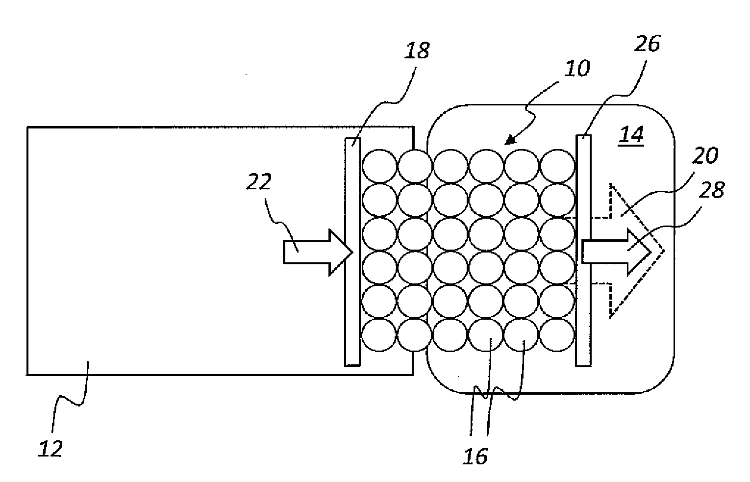
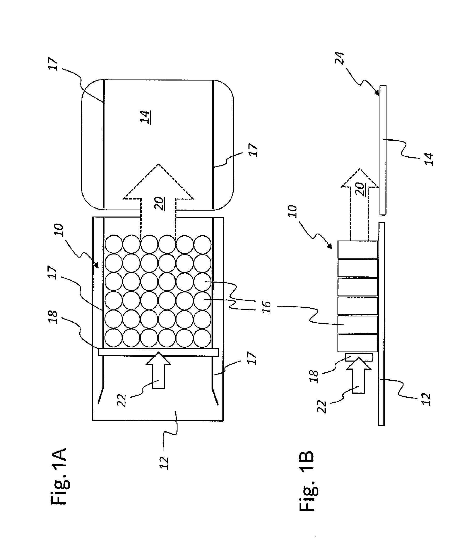
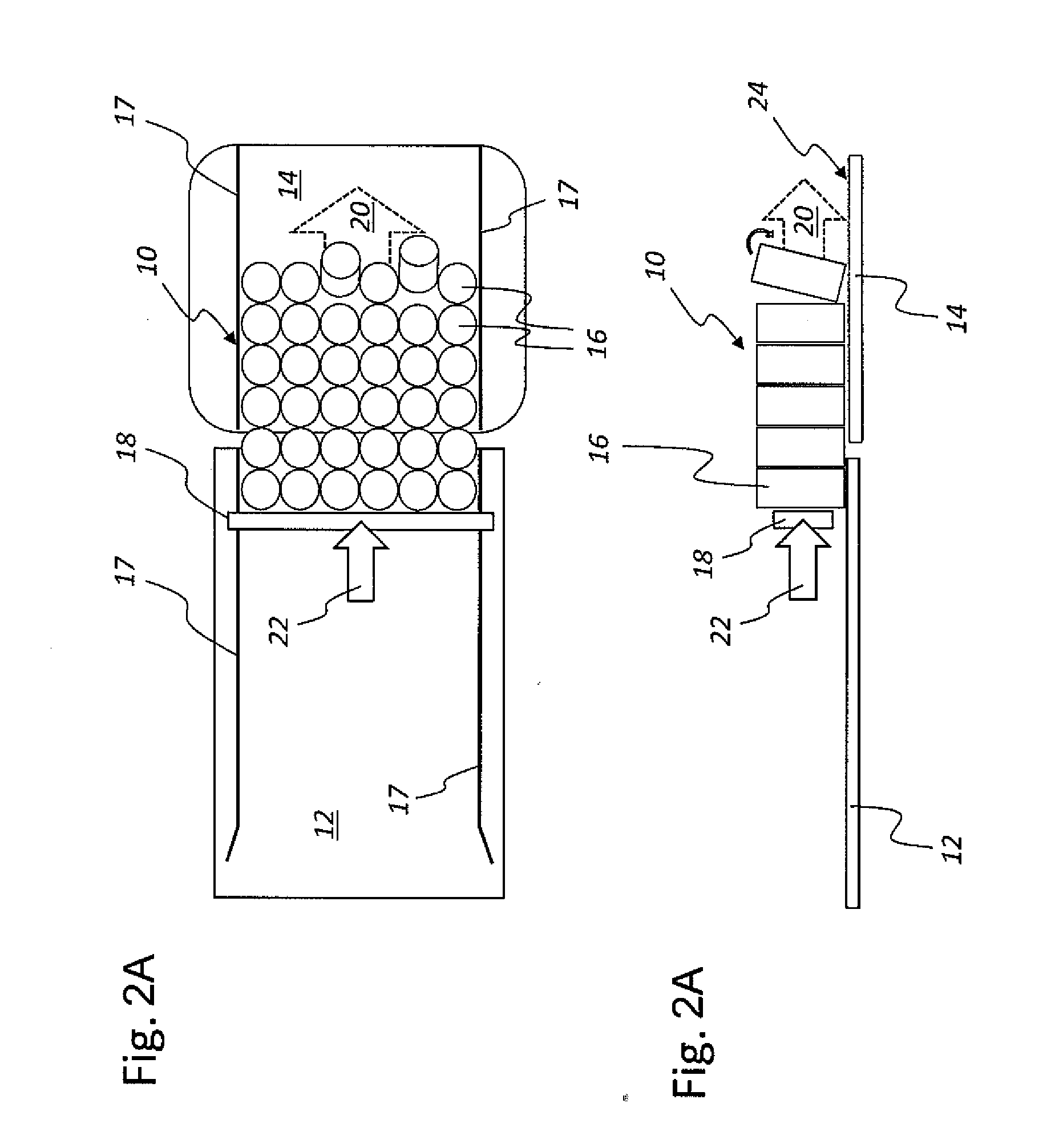
[0036]In a schematic top view (FIG. 1A) and a schematic side view (FIG. 1B), the illustrations in FIG. 1 show an article group or article layer 10 being horizontally shifted from a first position on a first module 12, for instance on a grouping table, which can be a part of a grouping system, to a second position on a second module 14, which can be, for instance, a lifting module or a loading station or the like. The article layer 10 shown here in the depicted exemplary embodiment co...


PUM


Abstract

A method and apparatus for horizontally shifting an article group or article layer, composed of a plurality of articles, from a first position and/or from a conveying movement into a second rest position while largely maintaining the relative positions of the articles in the article layer or group to each other, said transfer being effected by at least one first pusher bar engaging with the articles located at the back of the article group or article layer, as considered in relation to the conveying or feed direction. A support bar, which is at least temporarily allocated to the articles located at the front of the article group or layer, as considered in relation to the conveying direction, moves ahead at a slight distance from or abuts on the foremost articles of the article group or layer at least immediately before or on reaching the rest position.

Description

[0001]This claims the benefit of German Patent Application DE 10 2012 204 013.7, filed Mar. 14, 2012 and hereby incorporated by reference herein.[0002]The present invention relates to a method for horizontally shifting an article group by means of at least one pusher bar. The invention further relates to a corresponding apparatus.BACKGROUND[0003]Moving groups of articles by shifting them in a horizontal direction to a defined position by means of pusher bars or other suitable transfer means, or by movable support surfaces, involves a certain risk of the articles being dislodged in relation to each other within the group according to the speed of the shifting motion, in particular on reaching the end position. Under unfavorable conditions, in particular under rapid deceleration at the end of a transfer movement, individual articles may even topple over. In general, the risk of toppling over or becoming dislodged is greatest for the articles positioned foremost in transfer direction, ...

Claims


Application Information

Patent Timeline
Patent Type & Authority Applications(United States)
IPC IPC(8): B65G47/76B65G59/02B65G57/10
CPCB65G47/766B65G57/10B65G47/841B65B35/405B65G59/02
Inventor BEER, ERHARDOSTERHAMMER, MARTIN
Owner KRONES AG
Why Eureka
Try Eureka