

Zero artifact vascular clip method and apparatus
- Summary
- Abstract
- Description
- Claims
- Application Information
AI Technical Summary
Benefits of technology
Problems solved by technology
Method used
Image

Examples
Embodiment Construction
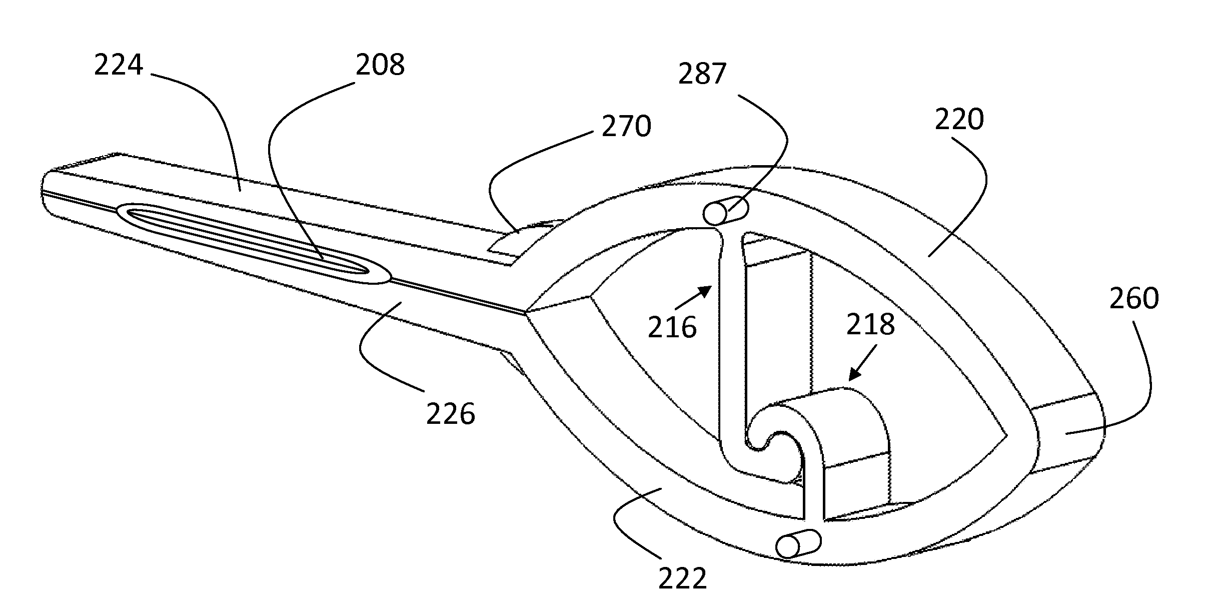
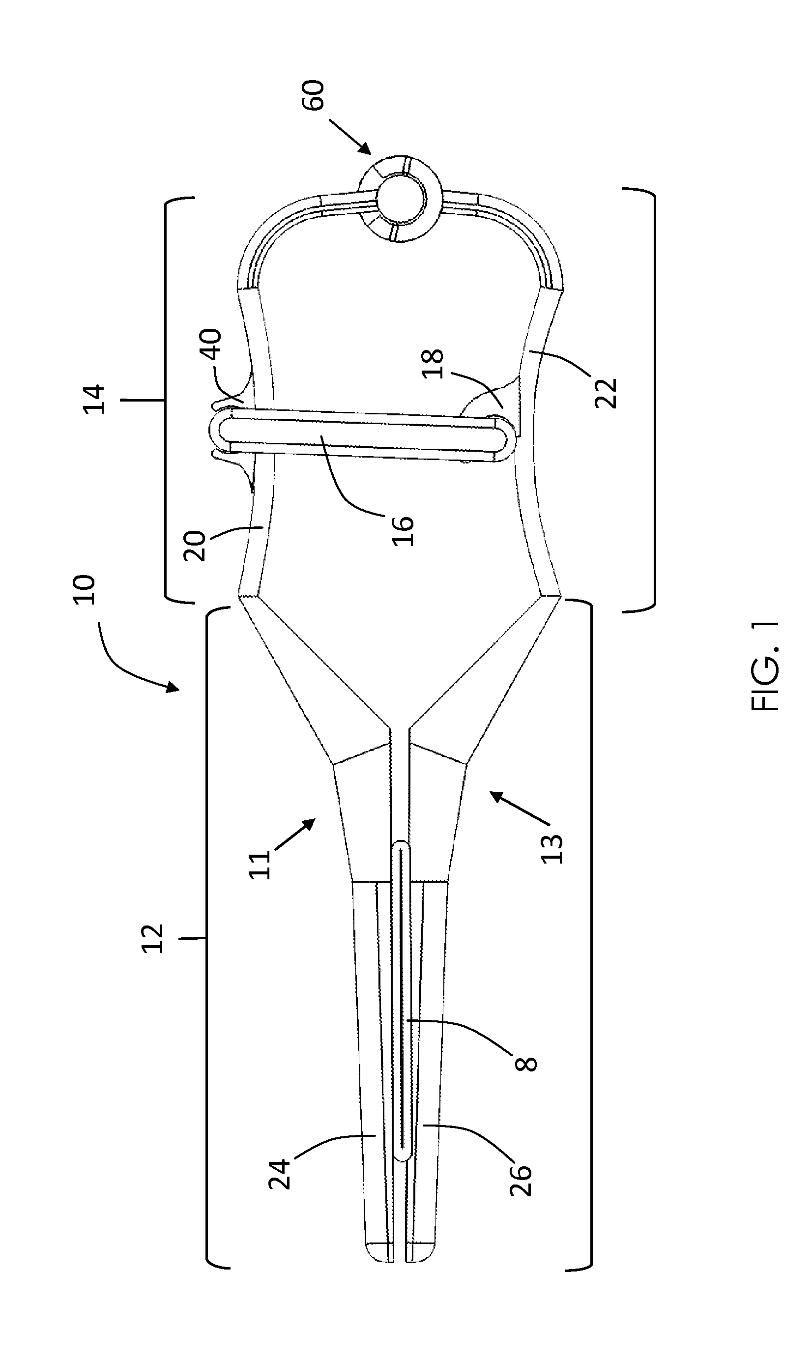
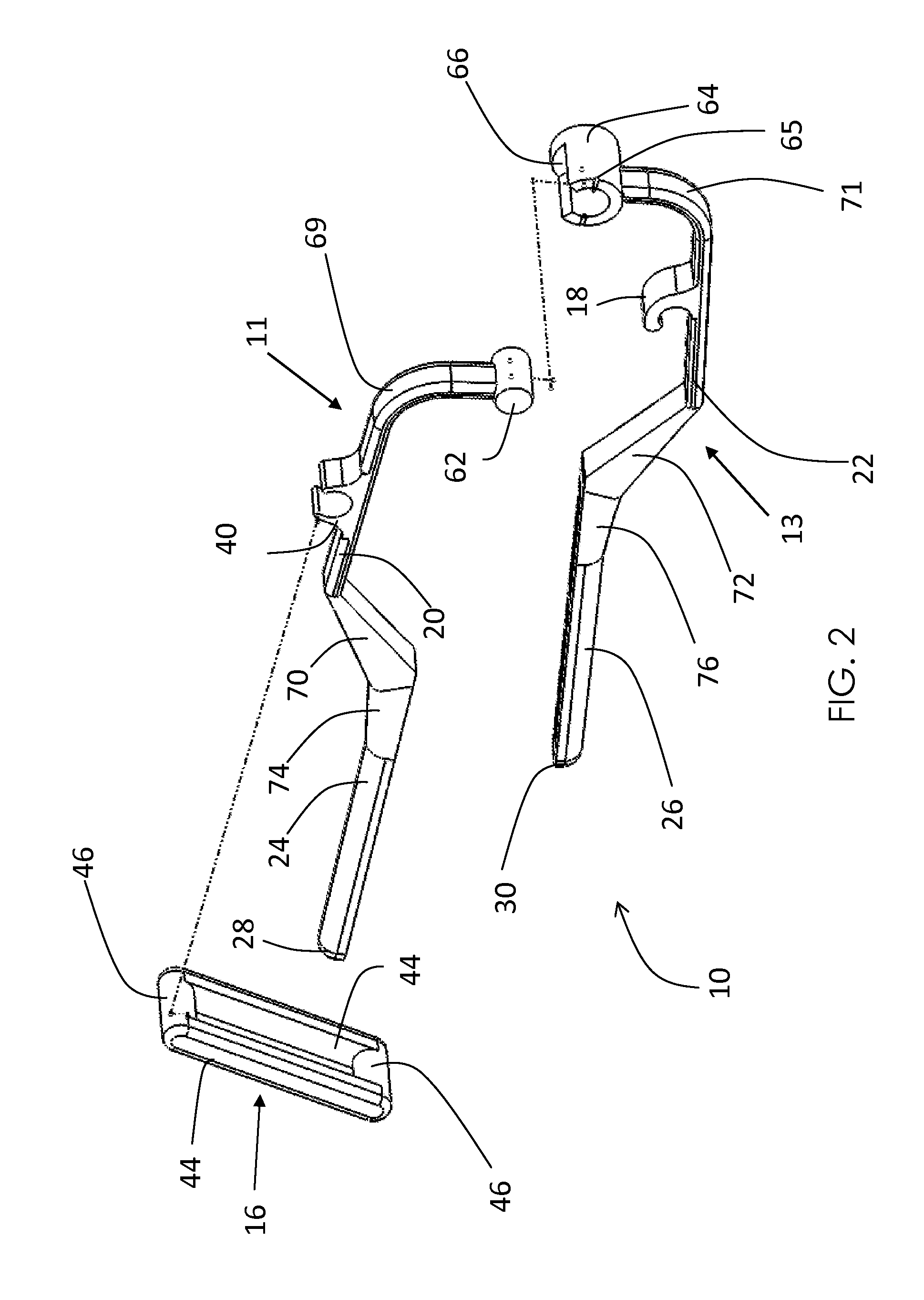
[0046]The vascular clip of the present invention may be used in a number of applications to cease blood flow from a vessel in the human body. The zero artifact features make the vascular clip particularly well suited for the treatment of aneurysms within the brain. Aneurysms, such as subarachnoid type, in the brain are treated typically by coiling or clipping. The number of cases is divided approximately 50 / 50 between the two methods. Clipped aneurysms are of interest for this innovation. Clipping using a vascular or aneurysm clip blocks blood flow so that the aneurysm will clot and cease expanding so as not to burst or leak. The clip clamps the proximal blood vessel that feeds the aneurysm. Metallic clips of the prior art are made by various manufacturers with variations in size, shape, and holding / clamping force, but typically the designs are the same with a torsional spring and clamp or jaw. Forces of the jaw or clamp are on the order of approximately 100 to 300 grams of force. T...
PUM
 Abstract
Description
Claims
Application Information