Electrically driven vacuum pump for a vehicle

a vacuum pump and electric drive technology, applied in the direction of machines/engines, electric control, braking systems, etc., can solve the problems of reducing the recovery time of brake vacuum, shortening the operational life of electrically driven vacuum pumps, and increasing the air flow rate, so as to achieve less effort and more comfort

Inactive Publication Date: 2013-09-26
FORD GLOBAL TECH LLC
View PDF6 Cites 10 Cited by
  • Summary
  • Abstract
  • Description
  • Claims
  • Application Information

AI Technical Summary

Benefits of technology

[0001]Vacuum may be consumed by various devices in a vehicle. For example, vacuum may be utilized in brake assist or a power braking system to multiply force that is applied by a vehicle operator to a brake pedal. The multiplied force may be applied to a master brake cylinder to provide vehicle braking. The brake assist may allow the vehicle operator to apply the brakes with less effort and more comfort relative to unassisted braking. In some implementations, at least some vacuum for brake assist may be provided by an electrically driven vacuum pump (EVP).
[0003]However, the inventors herein have recognized potential issues with such an approach. For example, since air is merely circulated to and from the intake manifold downstream of the turbocharger, a differential pressure and correspondingly the air flow rate of the electrically driven vacuum pump is low. Accordingly, the electrically driven vacuum pump may be operated more frequently to meet the vacuum consumption demands of the brake booster. This may result in a shorter operational lifespan of the electrically driven vacuum pump. Moreover, the low air flow rate may result in a slow rate of vacuum production when the electrically driven vacuum pump is turned on.
[0005]By selectively routing air exhausted from the electrically driven vacuum pump upstream of the turbocharger or into the intake manifold, air may be exhausted to a lowest available pressure. Accordingly, the pressure differential and correspondingly the air flow rate of the electrically driven vacuum pump may be increased relative to a configuration that merely routes air to the intake manifold downstream of the turbocharger. In this way, the electrically driven vacuum pump may be operated less frequently, and the operational lifespan of the electrically driven vacuum pump may be increased relative to the configuration that merely routes air to the intake manifold downstream of the turbocharger.
[0006]Furthermore, the increase of the air flow rate reduces brake vacuum recovery time. In this way, a suitable amount of vacuum may be provided for repeated brake actuations. Moreover, the increased flow rate generates a greater amount of vacuum that may facilitate the downsizing of the electrically driven vacuum pump by a pump size. In this way, a cost and weight reduction of the vehicle may be achieved.

Problems solved by technology

In particular, during operation of the electrically driven vacuum pump, air is pumped from the brake booster, through the electrically driven vacuum pump, and exhausted to the intake manifold downstream of the turbocharger.
However, the inventors herein have recognized potential issues with such an approach.
This may result in a shorter operational lifespan of the electrically driven vacuum pump.
Moreover, the low air flow rate may result in a slow rate of vacuum production when the electrically driven vacuum pump is turned on.
Furthermore, the increase of the air flow rate reduces brake vacuum recovery time.

Method used


Image

  • Electrically driven vacuum pump for a vehicle
  • Electrically driven vacuum pump for a vehicle
  • Electrically driven vacuum pump for a vehicle

Examples


Embodiment Construction

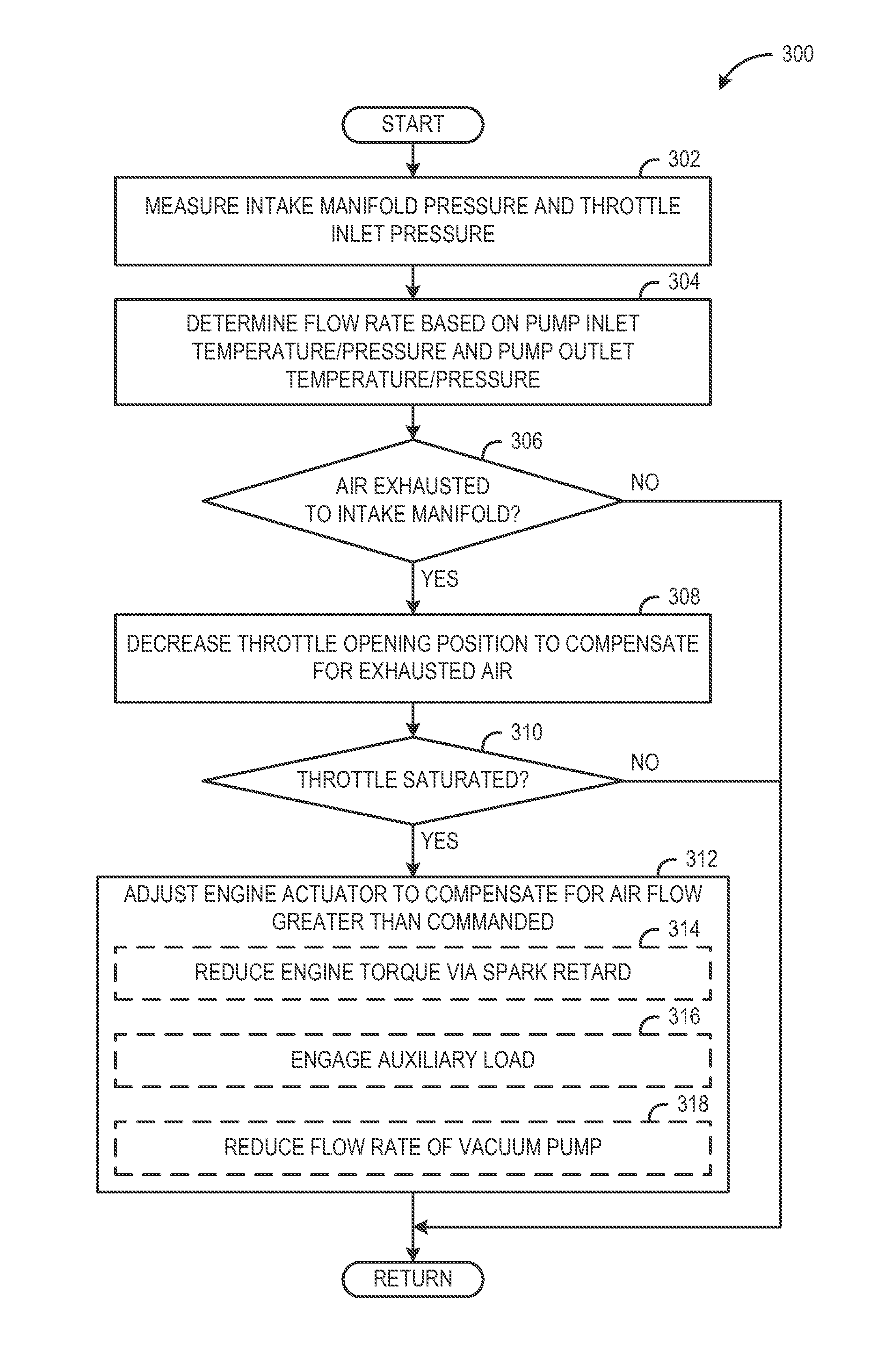
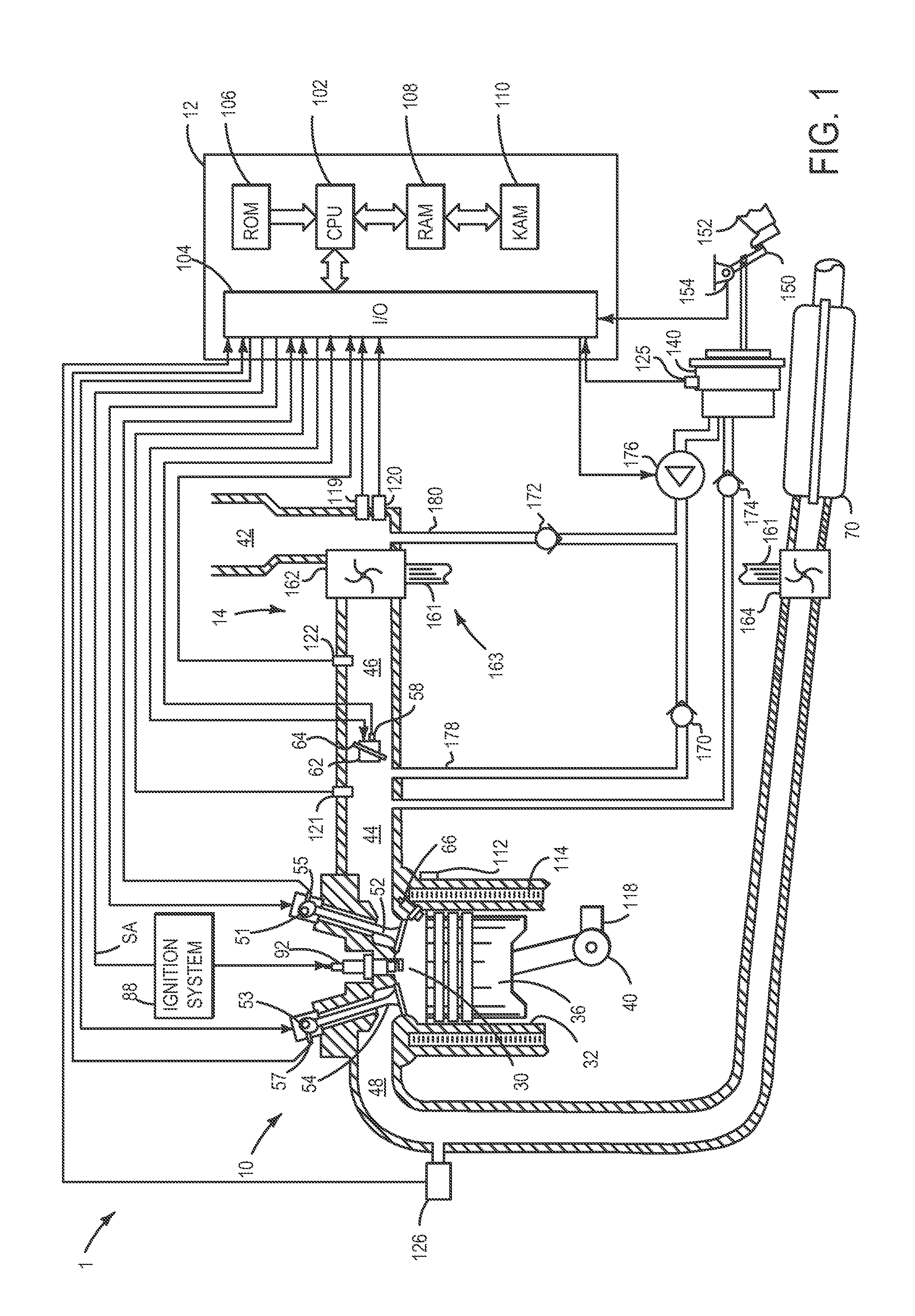
[0012]The present description relates to systems and methods for supplying vacuum to a vacuum consumption device of a vehicle using an electrically driven vacuum pump. More particularly, the present description relates to selectively routing air flow from the electrically driven vacuum pump to a lowest available pressure of the vehicle based on operation conditions.

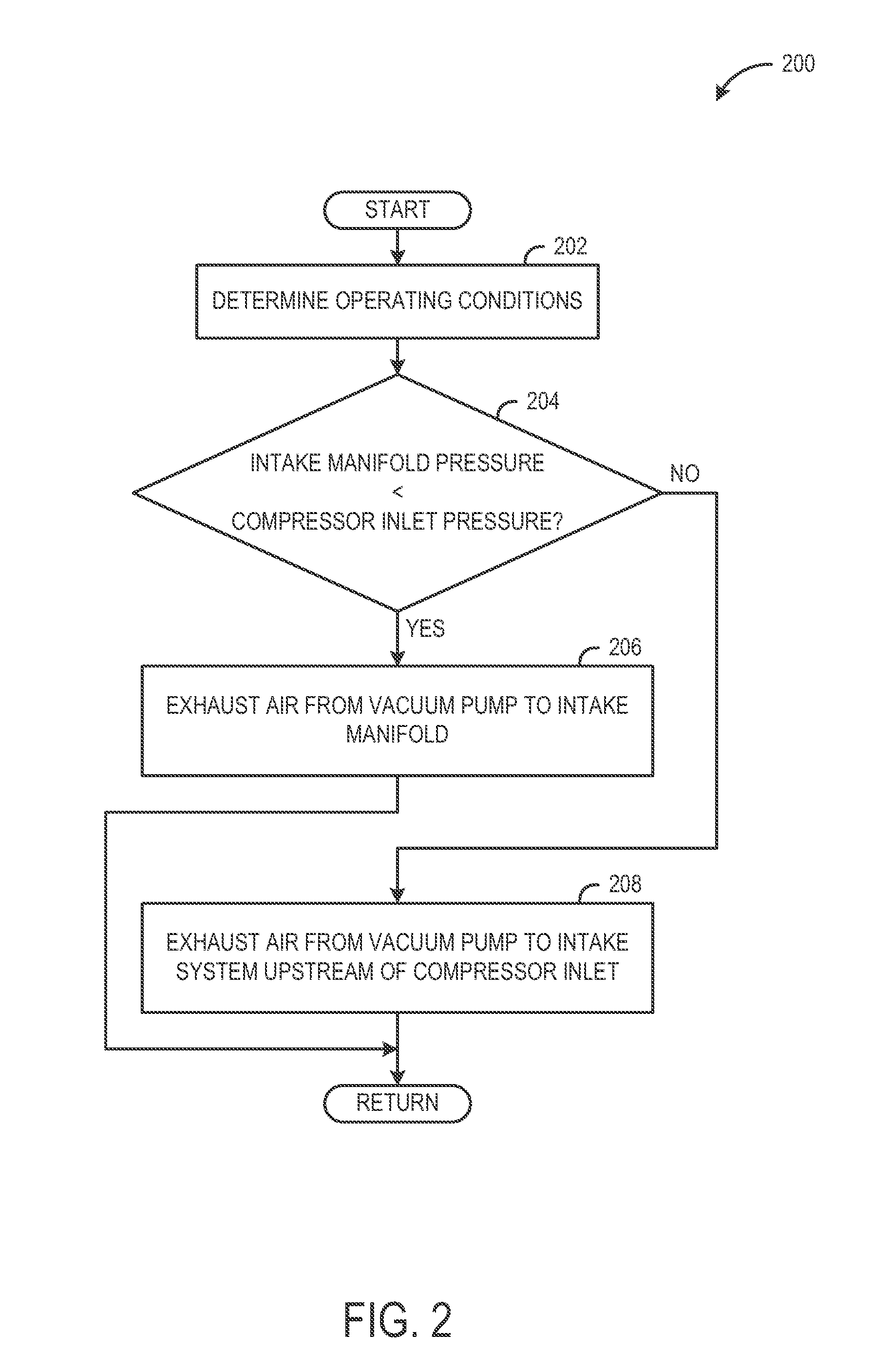
[0013]As shown in FIGS. 1-2 an electrically driven vacuum pump may selectively route air upstream and downstream of a turbocharger in a boosted engine. In one example, air may be routed from the electrically driven vacuum pump to the intake manifold downstream of the turbocharger when a pressure in the intake manifold is lower than a pressure in the air intake system upstream of the turbocharger. On the other hand, air may be routed from the electrically driven vacuum pump to the air intake system upstream of the turbocharger when a pressure in the air intake system upstream of the turbocharger is lower than a pressure in...


PUM


Abstract

A system for supplying vacuum to a vacuum consumption device of a vehicle is disclosed. The system includes an electrically driven vacuum pump selectively routing air to an air intake system upstream and downstream of a turbocharger.

Description

BACKGROUND AND SUMMARY[0001]Vacuum may be consumed by various devices in a vehicle. For example, vacuum may be utilized in brake assist or a power braking system to multiply force that is applied by a vehicle operator to a brake pedal. The multiplied force may be applied to a master brake cylinder to provide vehicle braking. The brake assist may allow the vehicle operator to apply the brakes with less effort and more comfort relative to unassisted braking. In some implementations, at least some vacuum for brake assist may be provided by an electrically driven vacuum pump (EVP).[0002]In one example, an electrically driven vacuum pump is operable to pump air from a boosted engine to provide vacuum for a brake booster. In particular, during operation of the electrically driven vacuum pump, air is pumped from the brake booster, through the electrically driven vacuum pump, and exhausted to the intake manifold downstream of the turbocharger.[0003]However, the inventors herein have recogni...

Claims


Application Information

Patent Timeline
Patent Type & Authority Applications(United States)
IPC IPC(8): B60T13/46
CPCB60T13/46B60T13/52Y02T10/144F02D41/021F02D41/0007B60T17/02Y02T10/12F02B75/00
Inventor PURSIFULL, ROSS DYKSTRA
Owner FORD GLOBAL TECH LLC
Why Eureka
Try Eureka