
Electric machine and method to retrofit an electric machine

Active Publication Date: 2013-09-26
GENERAL ELECTRIC TECH GMBH
View PDF3 Cites 2 Cited by
  • Summary
  • Abstract
  • Description
  • Claims
  • Application Information

AI Technical Summary

Benefits of technology

The invention aims to reduce the power needed to operate fans in an electric machine and prevent the formation of cool zones that could damage the machine.

Problems solved by technology

This causes a waste of power for operating the fans 9 and can also cause cool zones inside of the electric machine.
Therefore the temperature of the cooling fluid is not optimised.

Method used


Image

  • Electric machine and method to retrofit an electric machine
  • Electric machine and method to retrofit an electric machine
  • Electric machine and method to retrofit an electric machine

Examples


Embodiment Construction

[0020]In the following like reference numerals designate like or corresponding parts throughout the several views.

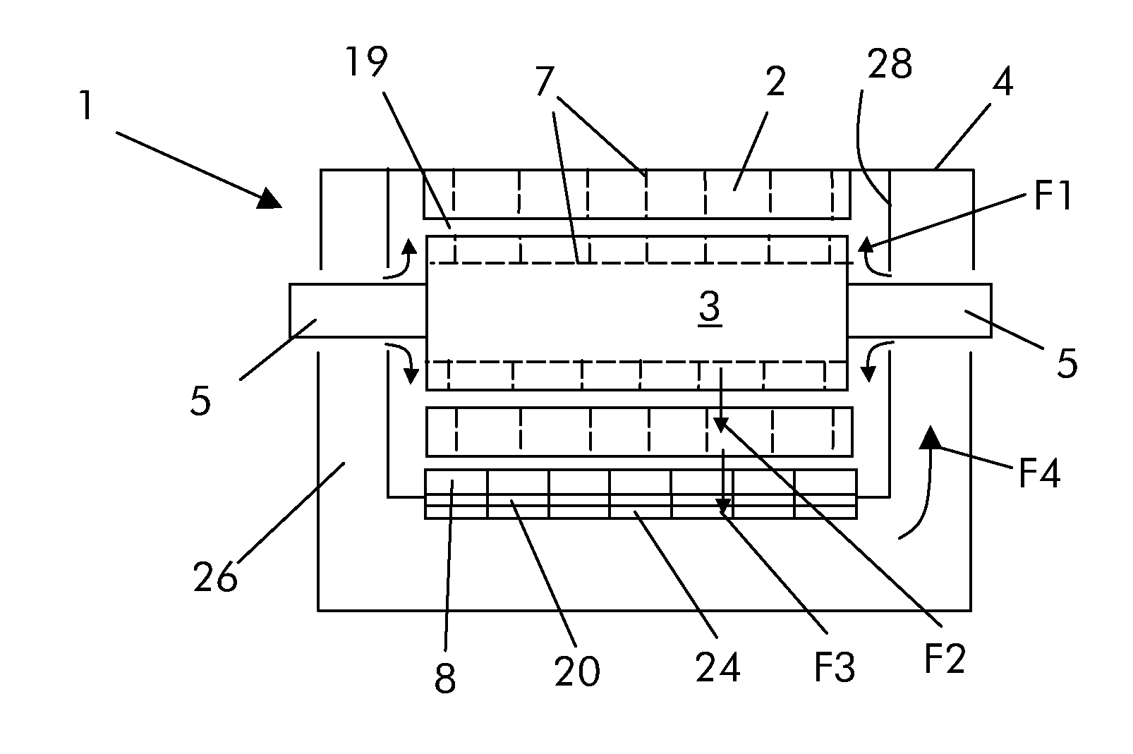
[0021]The electric machine 1 can be an electric generator such as a turbogenerator (i.e. a synchronous generator to be connected to a gas turbine or a steam turbine) a hydro generator (i.e. a synchronous generator to be connected to a hydro turbine), a different kind of generator (for example an asynchronous generator), a synchronous or asynchronous electric motor, and so on.

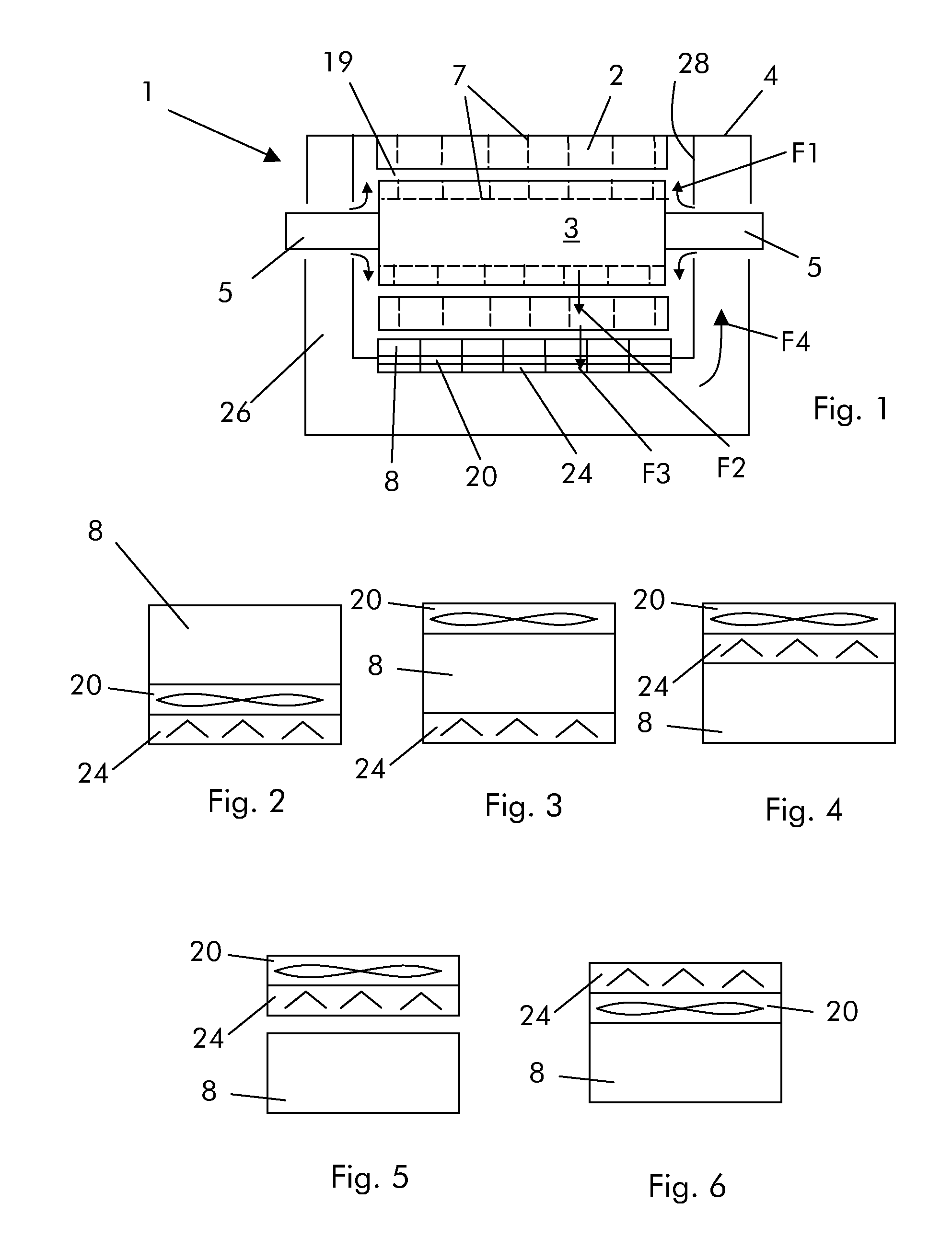
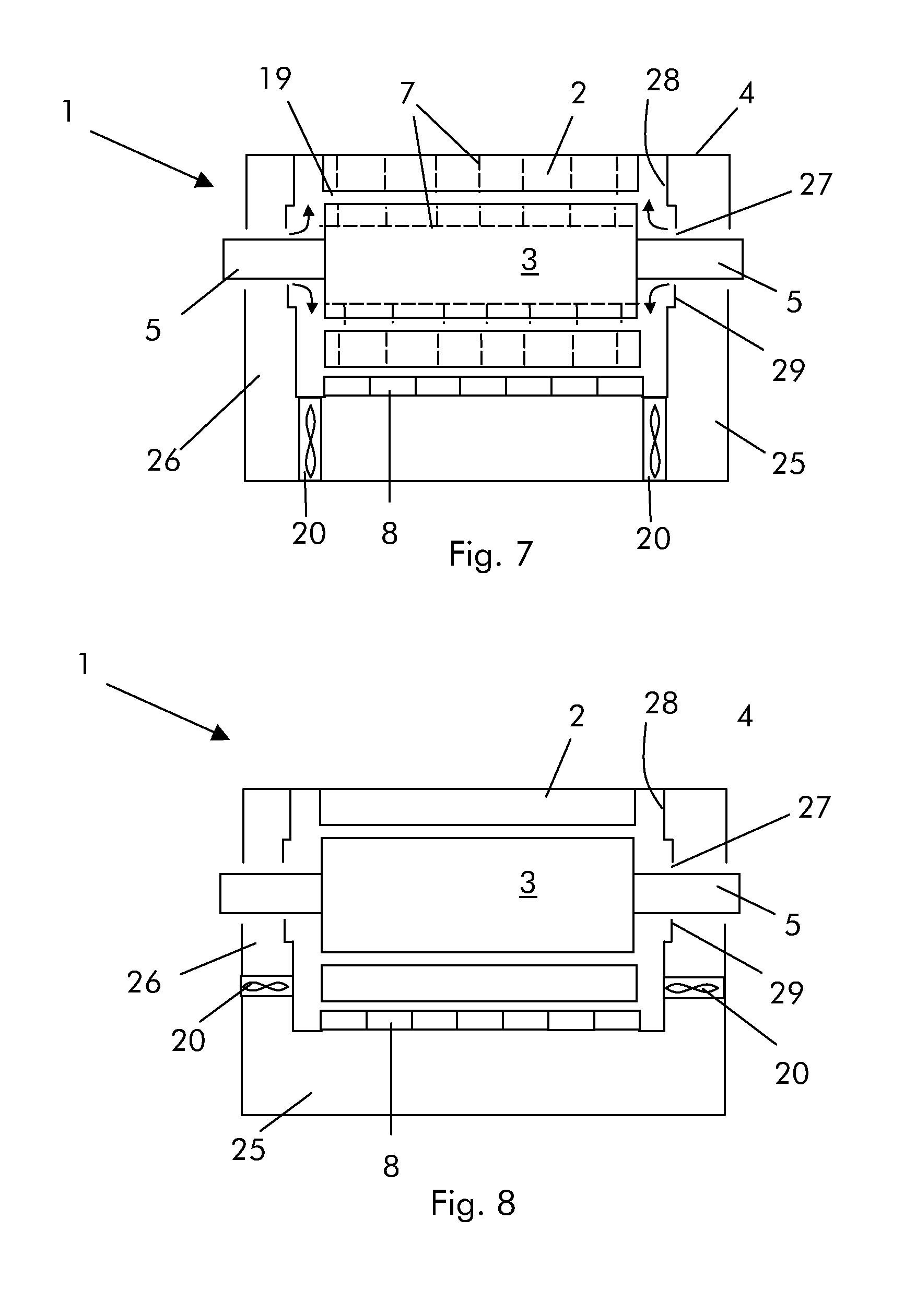
[0022]The electric machine 1 comprises a stator 2 and a rotor 3. The stator 2 and / or rotor 3 have a cooling circuit that can include channels (like the channels 7 in the drawings) but in different examples the cooling circuit can only include the gap 19 between the stator 2 and rotor 3 and passages to recirculate the cooling fluid like the lateral passages 26 shown in the drawings. In addition the coolers 8 are only provided when needed. Stator 2 and rotor 3 are housed in the casing 4 that also house...


PUM

PropertyMeasurementUnit
Pressureaaaaaaaaaa

Abstract

The electric machine (1) comprises a stator (2), a rotor (3), a cooling circuit for the stator (2) and / or rotor (3), fans (20) for cooling fluid circulation. The fans (20) are separated from the rotor (3).

Description

TECHNICAL FIELD[0001]The present disclosure relates to an electric machine and a method to retrofit an electric machine.[0002]The electric machine can be an electric generator such as a synchronous electric generator, an electric motor or other different rotating electric machines.BACKGROUND[0003]With reference to FIG. 9, rotating electric machines 1 have a stator 2 and a rotor 3 housed in a casing 4. From each end of the rotor 3 a shaft 5 extends. The stator 2 and rotor 3 are usually provided with a cooling circuit for taking away the heat generated during operation.[0004]The cooling circuit usually includes channels through the stator 2 and rotor 3 for a cooling fluid and coolers 8 to cool down the cooling fluid. The cooling fluid is the fluid contained in the casing 4 and can be air, hydrogen, argon or a different fluid. In addition, the electric machine also has one or more fans 9 to circulate the cooling fluid.[0005]The fans 9 are connected to the shafts 5 such that, during ope...

Claims


Application Information

Patent Timeline
IPC IPC(8): H02K9/04H02K15/00
CPCH02K9/04Y10T29/49009H02K9/12H02K15/0006H02K9/18
Inventor DE GRAAFF, TJERK MICHIEL
Owner GENERAL ELECTRIC TECH GMBH
Learn More