
Method and control device for operating a power takeoff

A technology of auxiliary power and output device, applied in auxiliary drive device, transportation and packaging, control device, etc., can solve the problems of wear and damage of transmission components, and achieve the effect of prolonging life.

Active Publication Date: 2020-05-19
ZF FRIEDRICHSHAFEN AG
View PDF4 Cites 0 Cited by
  • Summary
  • Abstract
  • Description
  • Claims
  • Application Information

AI Technical Summary

Problems solved by technology

Sustained loading can also lead to inflow of the mechanical clearance of the transmission element
This can lead to faster wear or even damage to the transmission components

Method used


Image

  • Method and control device for operating a power takeoff
  • Method and control device for operating a power takeoff

Examples


Embodiment Construction

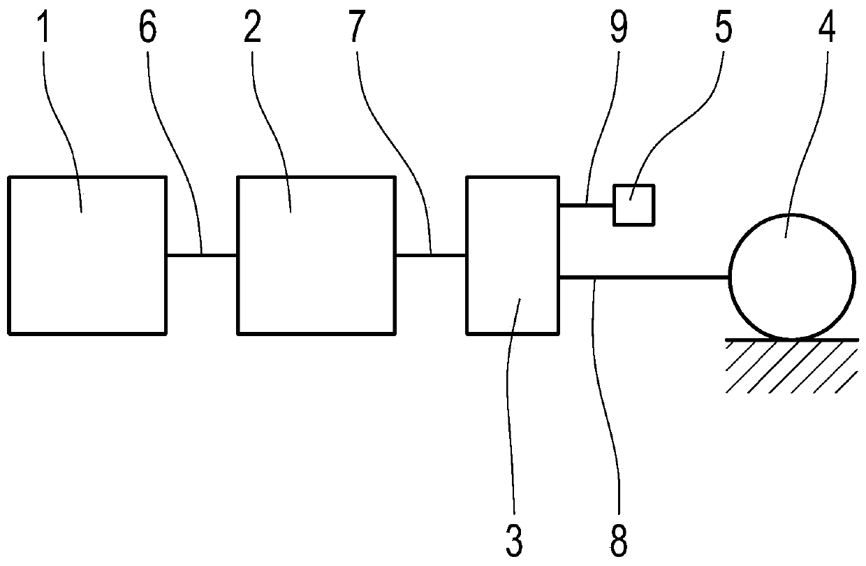
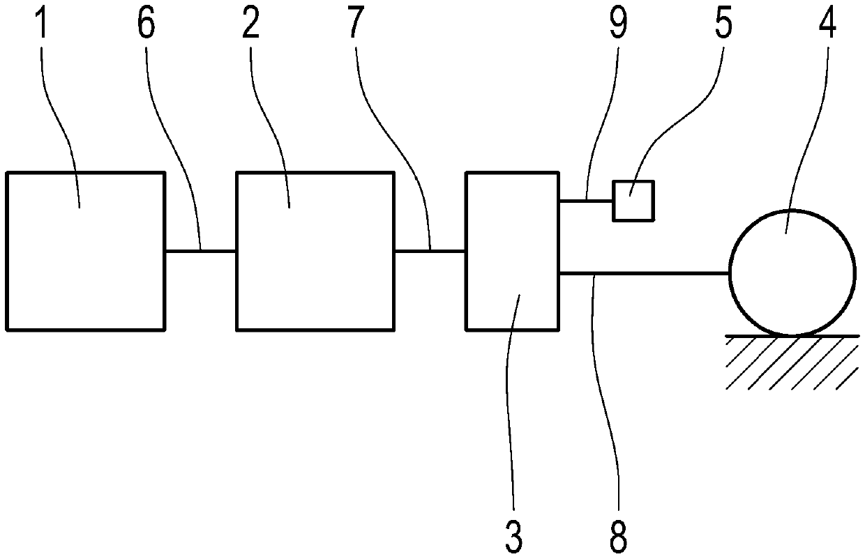
[0036] figure 1 A schematic diagram of a drive train of a motor vehicle designed as a commercial vehicle with a drive unit 1 designed as a gas or internal combustion engine is shown.

[0037] Furthermore, the motor vehicle comprises a transmission 2 and a transfer case 3 connected between the drive device 1 and the shaft output 4 .

[0038] The transmission 2 can be designed, for example, as an automatic transmission or an automated shift transmission. When the transmission 2 is designed as an automated shift transmission, it is known that a clutch (not shown here) can be connected between the drive unit 1 designed as a gas engine and the transmission 2 . When the clutch is open, the drive machine 1 is decoupled from the transmission 2 and when the clutch is closed, the drive machine 1 is coupled to the transmission 2 .

[0039] The drive unit 1 acts on a transmission input shaft 6 of the transmission 2 . The shaft output 6 is coupled to an output shaft 8 of the transmissio...


PUM


Abstract

The invention relates to a method for operating a power takeoff (5) in a drive train of a motor vehicle comprising at least one drive unit (1) and a transmission (2) connected between the drive unit (1) and an axial output (4), wherein a gear is engaged in the transmission (2) for operation of the power takeoff (5). During uninterrupted operation of the power takeoff (5), a shift to overdrive is performed automatically in the transmission (2) after expiration of a defined period of time.

Description

technical field [0001] The invention relates to a method of operating an auxiliary power take-off in the drive train of a motor vehicle according to the type defined in detail in the preamble of claim 1 . The invention also relates to a control device and a corresponding computer program product for carrying out the method. Background technique [0002] A motor vehicle designed as a commercial vehicle has a drive unit, a transmission, a shaft output and at least one auxiliary power take-off, wherein the auxiliary power take-off is connected between the drive unit and the shaft output. The auxiliary power take-off is also commonly referred to as PTO (Power take-off (power take-off)). In particular, transmissions of commercial vehicles usually have an auxiliary power take-off, via which the corresponding auxiliary equipment of the commercial vehicle can be connected and operated on the auxiliary output of the corresponding transmission. In this case, a corresponding drive to...

Claims


Application Information

Patent Timeline
Patent Type & Authority Applications(China)
IPC IPC(8): B60W30/184B60W10/11B60K17/28B60W10/30B60K25/06B60W30/188
CPCB60K17/28B60K25/06B60W10/11B60W10/30B60W30/184B60W30/1888B60W2710/1005
Inventor 安东·魏贝尔迪特尔·斯特龙克沃尔夫冈·施密特
Owner ZF FRIEDRICHSHAFEN AG
Learn More