
Cooling device with optional noise emission

A technology for cooling equipment and noise, applied in the field of refrigerators

Active Publication Date: 2019-07-12
V ZUG
View PDF9 Cites 0 Cited by
  • Summary
  • Abstract
  • Description
  • Claims
  • Application Information

AI Technical Summary

Problems solved by technology

[0004] Furthermore, the use of low-noise cooling devices, for example with vibration-reducing components, is known, but this is manifested in higher costs

Method used


Image

  • Cooling device with optional noise emission
  • Cooling device with optional noise emission

Examples


Embodiment Construction

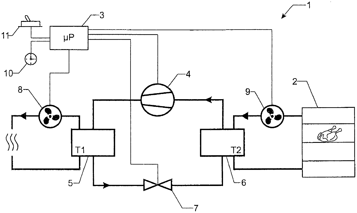
[0025] figure 1 An exemplary embodiment of the invention is shown in schematic form with the aid of a refrigerator for cold storage of food. The cooling devices 3 to 11 are designed in a known manner as heat pumps. The heat pump includes a compressor 4, a condenser 5, an evaporator 6, and a throttle valve 7 as main components. Refrigerant flows counterclockwise between the four main components 4 to 7 in the direction of the arrows shown. The condenser 5 is assigned an ambient air fan 8 and the evaporator 6 is assigned a cooling air fan 9 . The cooling air fan 9 assists in supporting heat transfer from the cold room 2 to the evaporator 6 by forcing convection and the ambient air fan 8 assists in supporting heat transfer from the condenser 5 to the surrounding environment. Here, the air flow forced by the fans 8 , 9 does not mix with the medium of the refrigerant circuit, but transfers heat via the heat exchanger.

[0026] In the present embodiment of the invention, the cool...


PUM


Abstract

The invention relates to a cooling device, in which a control device (3) of a cooling device (3 to 11) has a plurality of operating modes in order to be able to adjust the noise emission in a cooling device (1), in particular a refrigerator, according to requirements, wherein , at least two operating modes differ in their noise emissions with the same cooling performance. In heat pumps (3 to 11), for example, the flow resistance of the throttle valve (7) or the power stage of the compressor (4) is influenced in at least two operating modes.

Description

technical field [0001] The invention relates to a cooling device, in particular a refrigerator, for cold storage of food, which cooling device comprises at least one refrigerator compartment, a noise-generating cooling device and a control device for controlling the cooling device. Background technique [0002] Cooling appliances for the cold storage of food are known, in particular in the form of refrigerators or freezers, which include cooling devices which generate noise. [0003] Such cooling devices require a special design in order to avoid high noise emissions relative to the surrounding environment. While the problem of noise emission can be addressed through acoustic panels, this solution comes at the expense of effective volume. The same applies for better thermal insulation so that the cooling unit can operate at an average lower power level. [0004] Furthermore, the use of low-noise cooling devices is known, which has, for example, vibration-reducing component...

Claims


Application Information

Patent Timeline
Patent Type & Authority Patents(China)
IPC IPC(8): F25B49/02
CPCF25B49/02F25B2500/12
Inventor J·甘茨
Owner V ZUG
Learn More