Development system and method for creating a control unit program

a technology of development system and control unit, applied in the direction of program control, computer control, instruments, etc., can solve the problems of time-consuming and costly user training, and present time-consuming and difficult to allow a single user to perform a subtask, etc., to achieve simple understanding

Inactive Publication Date: 2013-09-26
DSPACE DIGITAL SIGNAL PROCESSING & CONTROL ENG
View PDF5 Cites 6 Cited by
  • Summary
  • Abstract
  • Description
  • Claims
  • Application Information

AI Technical Summary

Benefits of technology

[0014]An advantage of the invention is that a user is provided with a simple to understand and easy access to the complex architecture of a control unit program in the form of a compact structuring comprehensible to the user. As a result, control unit programs of the aforementioned type can also be created, configured, and thereupon simulated and tested by user groups, familiar only to a limited extent with the processes and build steps necessary for this. Hence, the user is supported during the implementation of his tasks, particularly during the creation of a control unit program. At the same time, a user is provided with a combination of display, access, and intervention options for a sequence of build process steps.
[0015]An electronic computer unit within the scope of the present invention can be understood to be a component of a computer system, for example, a personal computer (PC) or workstation. The electronic computer unit in this case can, for example, execute a program, so that the computer system is configured as a development system for the creation of a control unit program. The input unit, assigned to the electronic computer unit, can be configured, for example, as a keyboard and / or mouse of the computer. The display unit, assigned to the electronic computer unit, can be configured, for example, as a computer monitor or screen. To this end, the input unit and the display unit can each be linked wirelessly or by means of a connecting cable, e.g., system bus, to the electronic computer unit.
[0016]The first display area of the display unit can be designed, for example, as a rectangular subregion of the entire display area of the display unit. In the display area, the build process of the control unit program can be shown graphically as a flowchart. The successive build process steps in the build process can be shown, for example, as block elements arranged one above another when seen from the viewing direction. In this regard, the first build process step in the build process can be shown at the very top. The build process steps following the first build process step can then be arranged graphically following one another in the downward direction, i.e., below the first build process step. Connecting lines or connecting arrows can be shown between the block elements to make the order of the build process steps clear to the user.
[0017]The second display area of the display unit can also be shown as a rectangular subregion of the entire display area of the display unit. Elements of the model or the architecture of the control unit program are shown graphically in the display area. These elements can be displayed graphically in different ways, for example, by category or type of element in different form, color, brightness, and / or with a different texture. The build process steps can be selected, for example, by means of the input unit, which has the result that elements, assigned to the selected build process step, of the model of the control unit program are displayed in the second display area.
[0018]A user can select and moreover execute one or more build process steps by means of the input unit. As a consequence, for example, elements of the model of the control unit program can be created or updated.
[0019]The display areas can be arranged next to one another when seen in the view direction. For example, the first display area can be displayed on the left next to the second display area. In the case of rectangular display areas, therefore a rectangular overall view of two display areas arranged next to one another can be created. As a result, a user is given a clear orientation with respect to the flow of a build process. In the first display area (on left), the build process can be shown, for example, as a string of blocks, each of which represent a build process step. The orientation and selective access to relevant partial information or subfunctions are made possible for the user by this display.

Problems solved by technology

For example, in the case of a multitude of individual users, it is at present time-consuming and difficult to allow a subtask to be performed by a single user.
This is time-consuming and costly user training is often necessary.

Method used


Image

  • Development system and method for creating a control unit program
  • Development system and method for creating a control unit program
  • Development system and method for creating a control unit program

Examples


Embodiment Construction

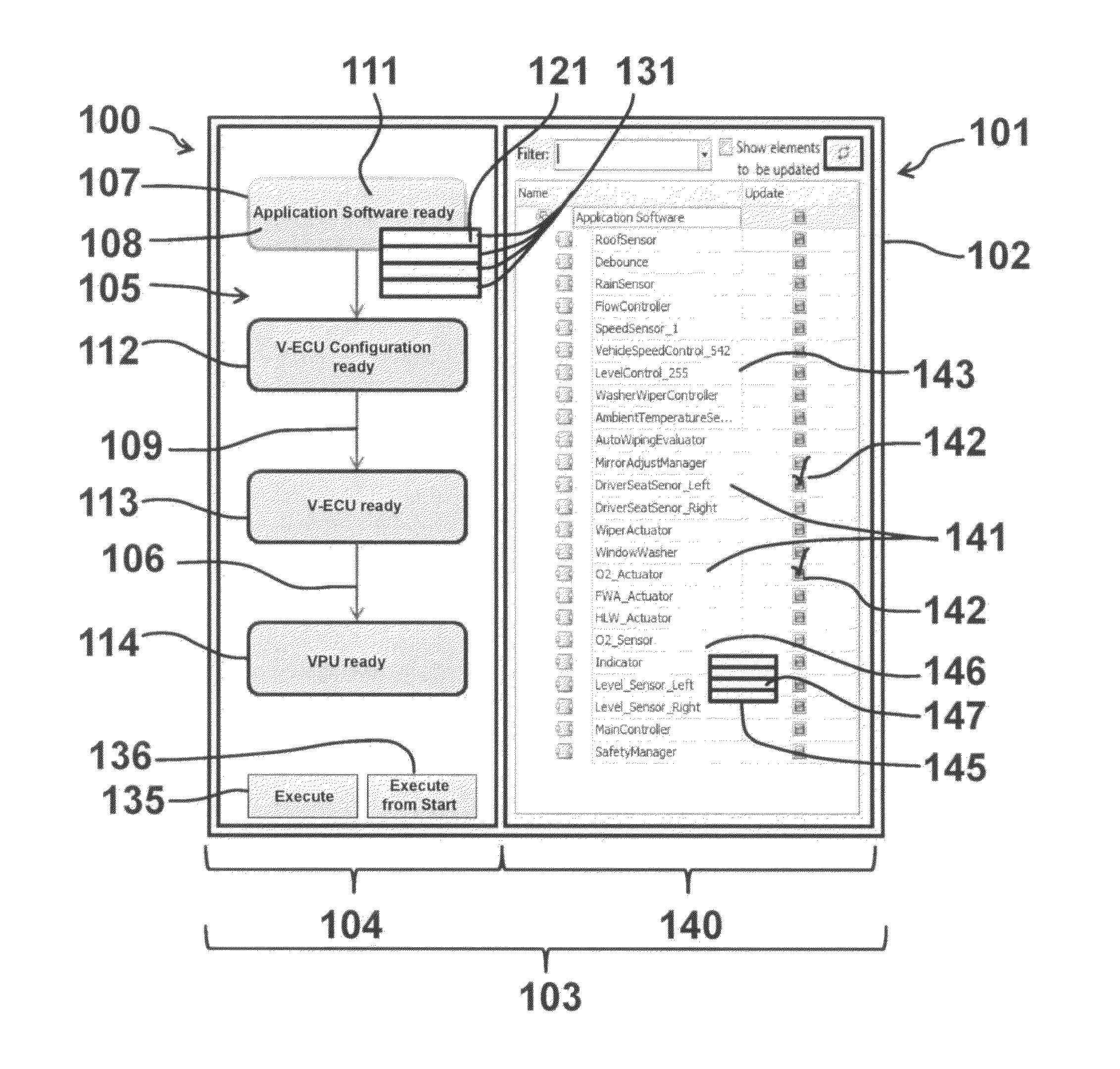
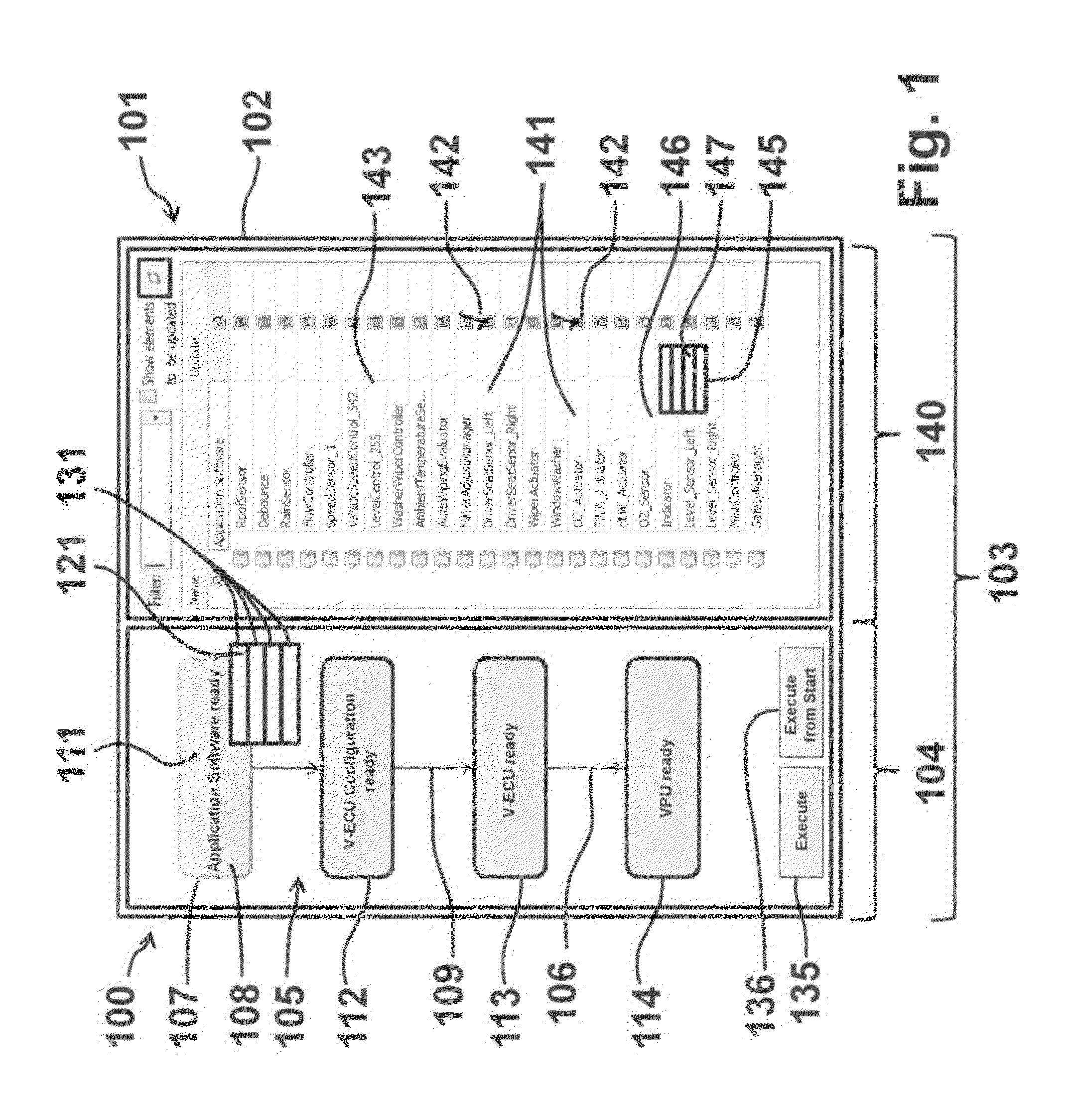
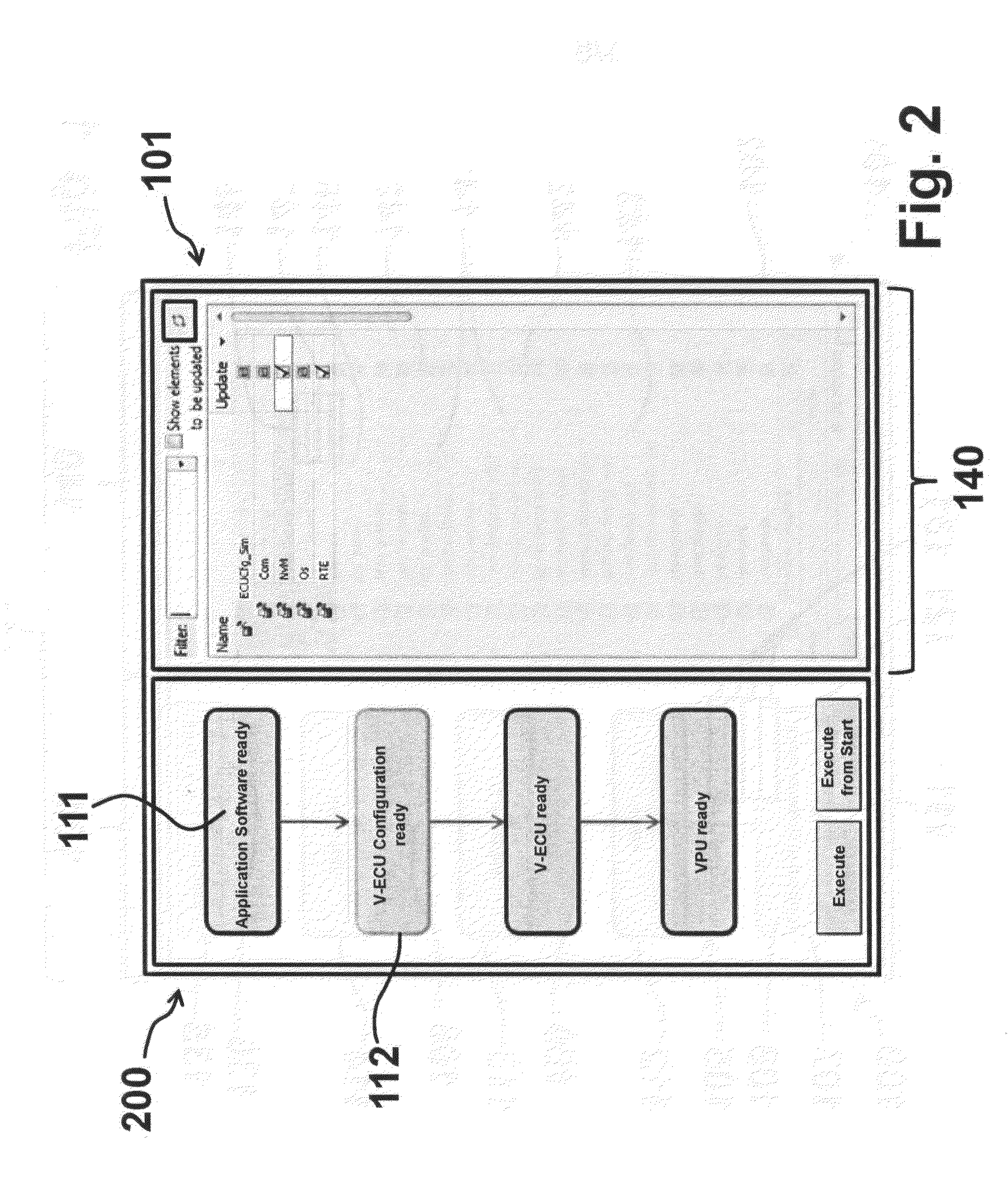
[0054]FIGS. 1 through 4 each show configurations 100, 200, 300, 400 of an exemplary embodiment of development system 101 of the invention. In particular, FIG. 1 shows a subregion 103 of a display unit 102. Subregion 103 of display unit 102 shows a first display area 104, which represents a left rectangular area of subregion 103. In first display area 104, display unit 102 graphically displays a build process 105 of a control unit program in the form of a flowchart 106. Flowchart 106 has a number of blocks 107, which are arranged one above the other when seen in the view direction and each of which represents a build process step 108. In the build process, the individual build process steps 108 follow one another. This is shown graphically by display unit 102 by means of connecting lines or connecting arrows 109, which connect blocks 107 to one another.

[0055]The individual build process steps 108 can be selected by means of an input unit. In the configuration shown in FIG. 1, build p...


PUM


Abstract

A development system for creating a control unit program, in which a control unit program is configured to control an electronic control unit in a vehicle. The development system includes an electronic computer unit, which is configured to generate the control unit program. The development system includes an input unit assigned to the electronic computer unit and a display unit assigned to the electronic computer unit. The display unit has a first display area and a second display area. At least one build process step can be executed by means of the development system.

Description

[0001]This nonprovisional application claims priority under 35 U.S.C. §119(a) to European Patent Application No. EP 12160249.4, which was filed in Europe on Mar. 20, 2012, and which is herein incorporated by reference.BACKGROUND OF THE INVENTION[0002]1. Field of the Invention[0003]The invention relates to a development system and a method for creating a control unit program, in which the control unit program is designed to control an electronic control unit in a vehicle.[0004]2. Description of the Background. Art[0005]Development systems and methods for creating control unit programs are known in the conventional art. They usually serve a user as a development tool for creating, developing, testing, simulating, and / or calibrating control unit programs, for example, for a real control unit or a virtual electronic control unit (V-ECU) and / or a virtual processing unit (VPU).[0006]A V-ECU is a virtual control unit, i.e., control unit software without direct hardware reference, which is ...

Claims


Application Information

Patent Timeline
Patent Type & Authority Applications(United States)
IPC IPC(8): G05B15/02
CPCG05B19/0426G05B15/02
Inventor ESCHMANN, MARIONESTEROW, VIKTORDEUTENBERG, GERNOT
Owner DSPACE DIGITAL SIGNAL PROCESSING & CONTROL ENG
Why Eureka
Try Eureka