Method and apparatus for a variable power ophthalmic lens

a variable power, ophthalmic lens technology, applied in the direction of intraocular lenses, spectales/goggles, instruments, etc., can solve the problems of design limitations in some applications, and achieve the effect of variable optical characteristics and thinner arcuate ophthalmic lenses

Active Publication Date: 2013-10-03
JOHNSON & JOHNSON VISION CARE INC
View PDF3 Cites 38 Cited by
  • Summary
  • Abstract
  • Description
  • Claims
  • Application Information

AI Technical Summary

Benefits of technology

[0009]The physical change of the liquid meniscuses may form or vary optical structures as it may be predetermined to thereby provide variable optical characteristics which can provide for a change in fo

Problems solved by technology

However, some of these designs may suffe

Method used


Image

  • Method and apparatus for a variable power ophthalmic lens
  • Method and apparatus for a variable power ophthalmic lens
  • Method and apparatus for a variable power ophthalmic lens

Examples


Embodiment Construction

[0019]The present invention provides for an ophthalmic lens with physical and chemical features conducive for inclusion in an ophthalmic lens, such as a contact lens or an intraocular lens. In the following sections detailed descriptions of embodiments of the invention will be given. The description of both preferred and alternative embodiments though are exemplary embodiments only, and it is understood that to those skilled in the art that variations, modifications, and alterations may be apparent. It is therefore to be understood that the exemplary embodiments do not limit the broadness of the aspects of the underlying invention as defined by the claims.

Glossary

[0020]In this description and claims directed to the presented invention, various terms may be used for which the following definitions will apply:

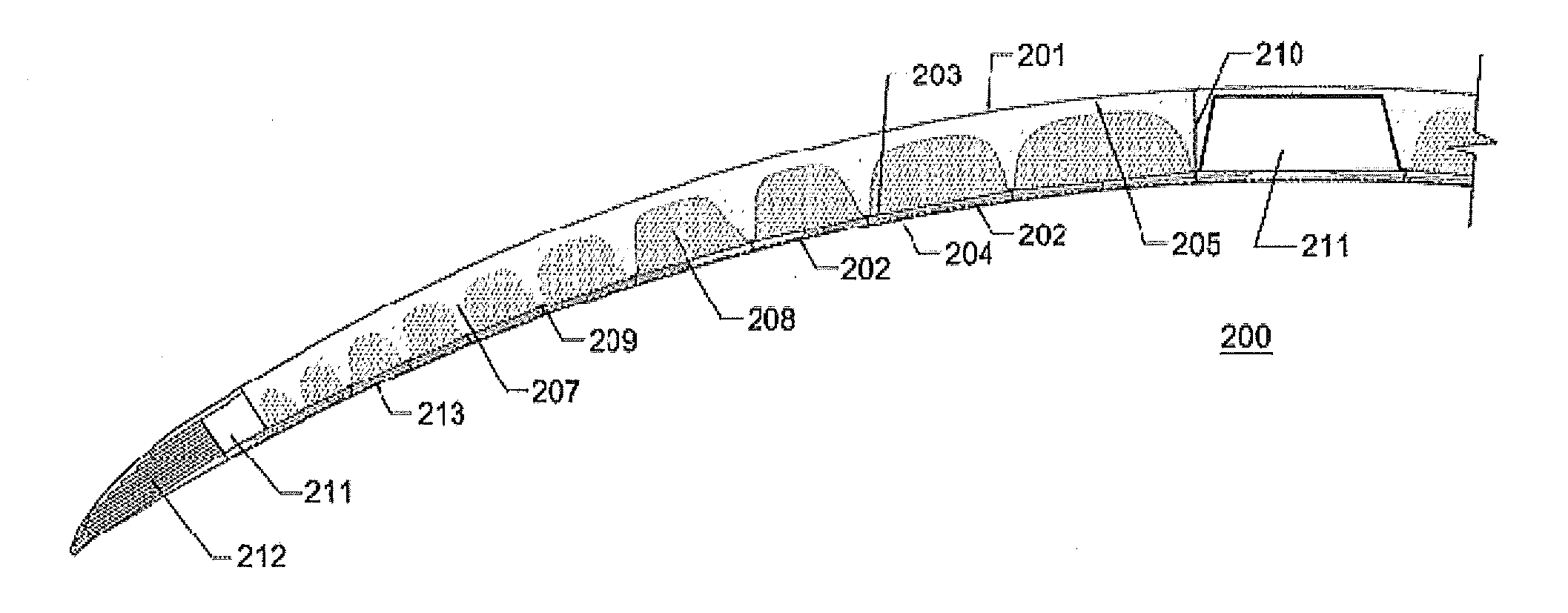
[0021]“Arcuate” as used herein, refers to a curve or bend like a bow shape.

[0022]“Concentric Annular Sections” as used herein, refers to one or more formed ring or spiral shaped ...


PUM


Abstract

This invention discloses methods and apparatus for providing an ophthalmic lens with diffractive/refractive variable optic structures. An energy source is capable of powering the variable optic included within the ophthalmic lens as it may be predetermined. In some embodiments, an ophthalmic lens is cast molded from a silicone hydrogel.

Description

CROSS REFERENCE TO RELATED APPLICATIONS[0001]This application claims priority to the U.S. Provisional Application No. 61 / 618,031, filed Mar. 30, 2012, the contents of which are relied upon and incorporated herein.FIELD OF USE[0002]The present invention relates generally to an Arcuate ophthalmic lens, more specifically, where the ophthalmic lens of this invention can include a series of Concentric Annular Sections. Said Concentric Annular Sections comprising variable liquid meniscuses in between a front curve Arcuate optical defining surface and a back curve Arcuate defining surface to provide a thinner variable power ophthalmic lens.BACKGROUND OF THE INVENTION[0003]Liquid meniscus lenses have been known in various industries. As discussed more fully below with reference to FIGS. 1A and 1B, known liquid meniscus lenses were engineered in cylindrical shapes with a perimeter surface formed by points at a fixed distance from an axis which is a straight line. Known examples of the use of...

Claims


Application Information

Patent Timeline
IPC IPC(8): G02C7/08G02F1/167
CPCG02C7/083G02B3/14G02C7/085G02C7/041G02B26/005G02C7/04G02C7/08A61F2/16G02C7/02A61F2/1624A61F2/1627A61F2/1654G02C2202/18G02C2202/20
Inventor PUGH, RANDALL B.OTTS, DANIEL B.DANIEL, JAMESWOOLEY, C. BENJAMINKERNICK, EDWARD R.FLITSCH, FREDERICK A.ARRUBLA, ANDRES F.
Owner JOHNSON & JOHNSON VISION CARE INC
Why Eureka
Try Eureka