
Method and apparatus for applying tension to a screen cloth on a vibrating screening machine

a technology of vibrating screening machine and tensioning screen cloth, which is applied in the direction of screening, chemistry apparatus and processes, solid separation, etc., can solve the problems of difficult rapid change of screening media or adjustment of tension force, system is often too unforgiving, and/or requires higher skill levels and/or more physical strength, etc., to achieve easy implementation, reduce slack induced internal movement of screen cloth, and variable resiliency characteristics

Active Publication Date: 2020-11-24
TEREX USA
View PDF11 Cites 0 Cited by
  • Summary
  • Abstract
  • Description
  • Claims
  • Application Information

AI Technical Summary

Benefits of technology

The present invention provides a method and system for reducing the movement of screen cloth and the contact between screen cloth and paddles or lateral cross-supports on a vibrating screen. It also provides an easily implemented system for applying a variable pulling force on a tensioned screen cloth and utilizing tensioner bar caps with variable resiliency characteristics. Additionally, it allows for efficient and cost-effective adjusting and measuring of tensioning forces applied to the screen cloth. The invention aims to improve the operation of a material processing vibrating screening machine by addressing the aforementioned needs and achieving the previously stated advantages.

Problems solved by technology

While these types of adjustably tensioned systems may have many advantages in particular applications, they also have some drawbacks.
For example, in many such vibrating screening machines, it is often not easy to quickly change the screening media or adjust the tension forces thereon, especially to objectively measurable levels of force.
These systems are often too unforgiving and / or require higher skill levels and / or more physical strength than is possessed by some persons operating and / or monitoring the vibrating screening machines.

Method used


Image

  • Method and apparatus for applying tension to a screen cloth on a vibrating screening machine
  • Method and apparatus for applying tension to a screen cloth on a vibrating screening machine
  • Method and apparatus for applying tension to a screen cloth on a vibrating screening machine

Examples


Embodiment Construction

[0032]Although described with particular reference to inclined multi-level end tensioned and side tensioned vibrating screens, the systems and methods, of the present invention, for applying and measuring tensioning forces to a screen cloth can be implemented in many different types of screen cloths and for many different vibrating screen applications.

[0033]In an embodiment, the system and method of the present invention described herein can be viewed as examples of many potential variations of the present invention which are protected hereunder.

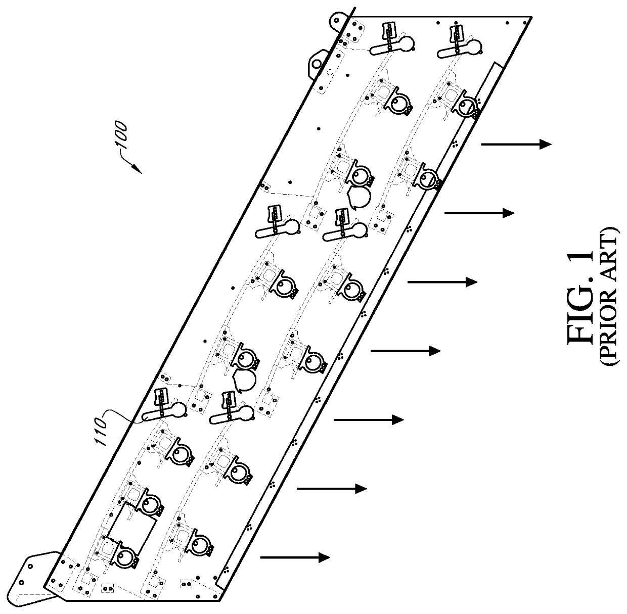
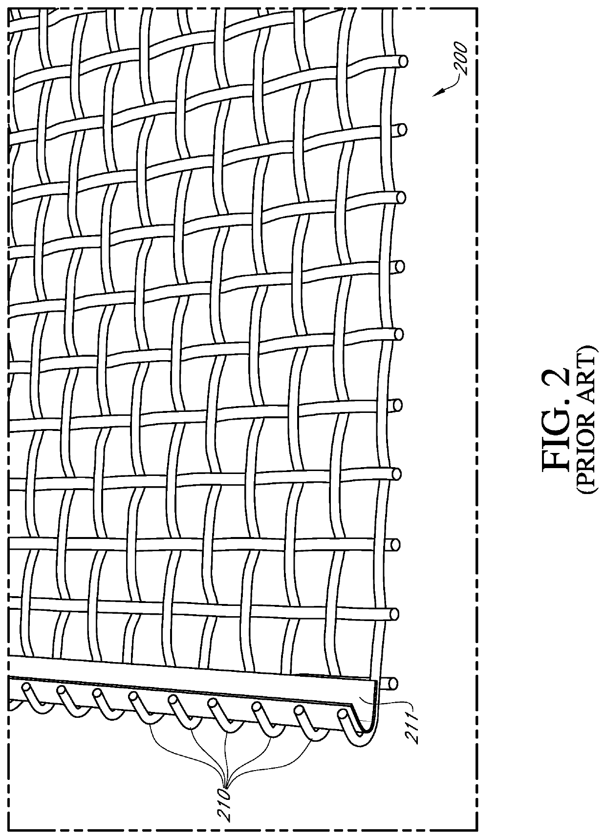
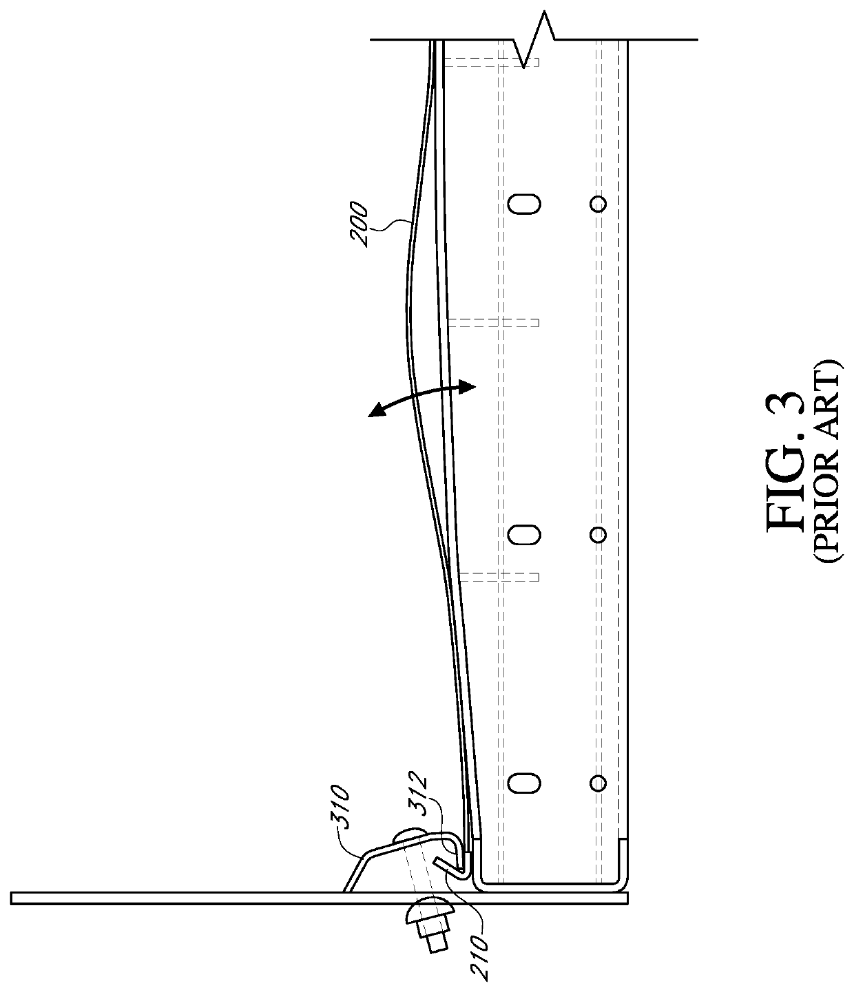
[0034]Now referring to the drawings wherein like numerals refer to like matter throughout and more particularly FIG. 1, there is shown a diagram illustrating a simplified version of just one vibrating screen 100 of the prior art. For the most part, these screens utilize vibration to agitate the mixture of aggregates to promote separation through various sized openings in the screening surfaces. Sorting is achieved by undersized particles pas...


PUM


Abstract

A variable resilience tension bar cap is disclosed for use in either, an end or side mounted tensioner in a vibrating screening machines used for material processing. A fluid filled hose or bladder may be disposed in a cap for a tensioner bar used to stretch wire cloth. Alternately a series of nested or replaceable resilient caps can be placed over the terminal end of a tensioner bar so that the cap is made to have a different resilience characteristics.

Description

CROSS REFERENCE TO RELATED APPLICATIONS[0001]The present application claims the benefit of the filing date of provisional patent application having Ser. No. 62 / 513,649 filed on Jun. 1, 2017 and provisional patent application having Ser. No. 62 / 575,746 filed on Oct. 23, 2017, both by the same inventor, which applications are incorporated herein in their entirety by this reference.FIELD OF THE INVENTION[0002]The present invention generally relates to material processing, and more particularly relates to vibrating screening machines, and, even more particularly, relates to adjustably tensioned screen cloths or wire cloths on vibrating screening machines.BACKGROUND OF THE INVENTION[0003]In the past, various adjustably tensioned screening media or screen cloths have been used in a wide variety of applications primarily to limit slack induced contact between the screen cloth and paddles or cross-supports which span the width of the screen. In many of such designs, it was common to have a ...

Claims


Application Information

Patent Timeline
Patent Type & Authority Patents(United States)
IPC IPC(8): B07B1/48
CPCB07B1/48
Inventor STROUP, DAVID BRYANSAUSER, EDWIN J
Owner TEREX USA
Learn More