Fluorescent lamp appliance, and lighting control apparatus of fluorescent lamp appliance

Inactive Publication Date: 2011-09-22
NIHON ENERGY INST
View PDF6 Cites 0 Cited by
  • Summary
  • Abstract
  • Description
  • Claims
  • Application Information

AI Technical Summary

Benefits of technology

[0037]Accordingly, for the fluorescent lamp appliances having different characteristics, it is possible to turn on one fluorescent lamp and to turn off the other fluorescent lamp by selecting the inductor, and thus it is possible to reliably switch the 2-lamp lighting and the 1-lamp lighting by the ON/OFF operation of the power supply switch.
[0038]As a result, in most commercially available 2-lamp serial-type fluorescent lamp appliances, one lamp can be turned off and the other lamp can be turned on when bright illumination is not necessary, such as in the daytime. Accordingly, it is possible to save electric power, and thus it is possible to save energy as a whole by cutting power consumption. When bright illumination is required, such as at nighttime, it is possible to perform illumination at the necessary brightness by turning on two lamps. In addition, it is conceivable to use a re

Problems solved by technology

In these 2-lamp serial-type fluorescent lamp appliances, the dummy tube is used, and thus the dummy tube has to be replaced wi

Method used


Image

  • Fluorescent lamp appliance, and lighting control apparatus of fluorescent lamp appliance
  • Fluorescent lamp appliance, and lighting control apparatus of fluorescent lamp appliance
  • Fluorescent lamp appliance, and lighting control apparatus of fluorescent lamp appliance

Examples


second embodiment

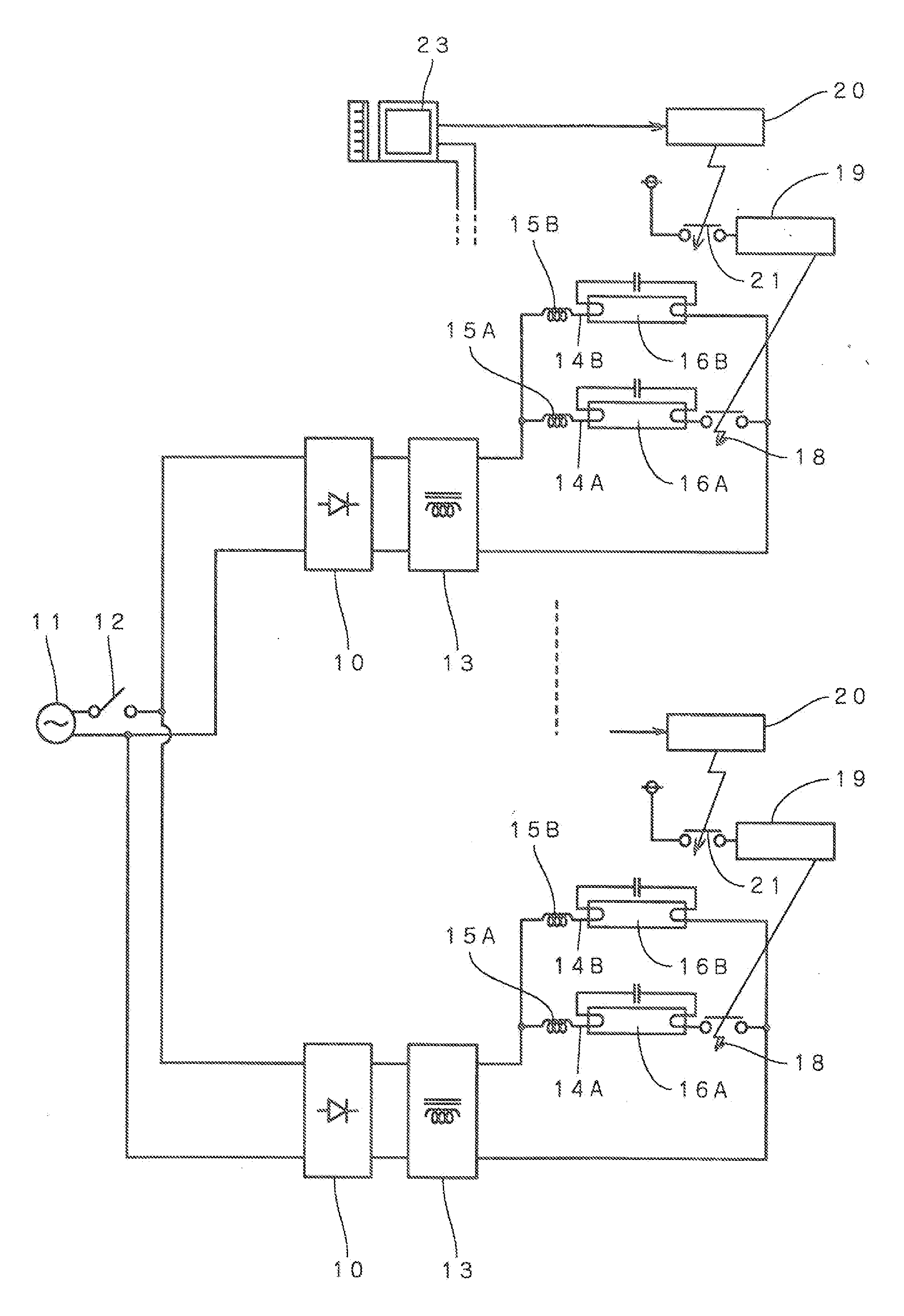
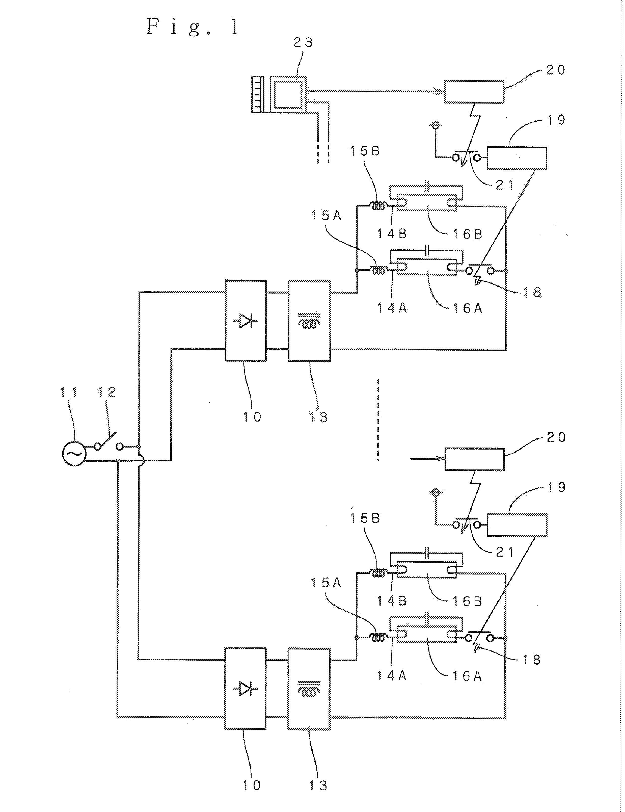
[0083]FIG. 6 to FIG. 8 show a In the figures, a power supply circuit is provided with a power supply switch (not shown), and uses an alternating current voltage of the commercial power supply, as an input. The output voltages H and N of the power supply circuit are input to the known inverter-type stabilizer 110, thereby outputting a high-frequency voltage.

[0084]Two current-carrying circuits 111A and 111B are connected to the output terminals of the inverter-type stabilizer 110 in series to the output terminals and in series to each other, and the two current-carrying circuits 111A and 111B are connected to the fluorescent lamps 112A and 112B. The current-carrying circuits 111A and 111B and the fluorescent lamps 112A and 112B have known configurations, and detailed description thereof is omitted.

[0085]Light turning-off circuits 113A and 113B are connected to the two fluorescent lamps 112A and 112B to electrically connect both terminals thereof, and two pairs of connection terminals...

first embodiment

[0105]The power supply input of the first control circuit 117 is connected to the normally closed-type relay contact point 130, and the relay contact point 130 is opened or closed by the second control circuit 131. The second control circuit 131 employs the same configuration as that of the second control circuit 20 of the first embodiment, and opens and closes the relay contact point 130 by the instruction signal of the PC (not shown).

[0106]Accordingly, the 2-lamp lighting and the 1-lamp lighting of the fluorescent lamp fixture can be switched by a PC, and thus it is possible to exert fine control of performing the 2-lamp lighting at a desired place and a desired time and switching to the 1-lamp lighting at other places and times.

[0107]In the example, the first control circuit 117 and the relay contact point 115 are mounted on the board 118, the board 118 and the second control circuit 130 are built in the same case, and the board 118 is provided with the connection terminals 114A ...


PUM


Abstract

The present Invention provides 2-lamp parallel-type and 2-lamp serial-type fluorescent lamp fixtures, in which 2-lamp lighting and 1-lamp lighting are switchable according to an ON/OFF operation of a power supply switch. In a 2-lamp parallel-type or 2-lamp serial-type fluorescent lamp fixture provided with an inverter-type stabilizer, 2-lamp lighting and 1-lamp lighting are switched by a first control circuit (19, 117) operated according to an ON/OFF operation of a power supply switch (12). In the case of the 2-lamp parallel-type fluorescent lamp fixture, the switching is performed by a switching means (18). In the case of the 2-lamp serial-type fluorescent lamp fixture, the switching is performed by light turning-off circuits (113A, 113B) electrically connecting both terminals of a fluorescent lamp. A second control circuit (20, 131) may be provided to switch the 2-lamp lighting and the 1-lamp lighting of the fluorescent lamps according to an external instruction of a PC or the like.

Description

TECHNICAL FIELD[0001]The present invention relates to a fluorescent lamp appliance, and more particularly, to a 2-lamp parallel type and 2-lamp serial type fluorescent lamp appliance in which 2-lamp lighting and 1-lamp lighting can be switched to each other.BACKGROUND ART[0002]There are many cases where a plurality of 2-lamp fluorescent lamp appliances are installed on the ceilings in offices, stores, factories, and the like to illuminate the whole interior. As such 2-lamp fluorescent lamp appliances, there are a serial-type appliance and a parallel-type appliance, but the serial-type appliances are put into wide use as illumination equipment from the viewpoint of excellent performance and price, and the parallel-type appliances, which can be easily controlled to be turned on and off, are widely employed as signboards such as outdoor billboards (Patent Literature No. 1 & No. 2).[0003]Recently, energy saving is required, regarding illumination, when bright illumination using 2 lamps ...

Claims


Application Information

Patent Timeline
IPC IPC(8): H05B37/02
CPCH05B37/0281Y02B20/42H05B41/42H05B41/282H05B47/16Y02B20/40
Inventor HOTTA, SHIGEMI
Owner NIHON ENERGY INST
Why Eureka
Try Eureka