High-precision remote optical path switch method and system

A high-precision technology for optical path switching, applied in the field of optical network communication, can solve the problems of inability to realize centralized and long-distance control of protection units, low accuracy, and small controllable range of switching thresholds, so as to achieve accurate and reliable optical path switching and realize remote Centralize management and improve performance that is difficult to accurately measure

Inactive Publication Date: 2010-07-28
SHANDONG UNIV
View PDF1 Cites 19 Cited by
  • Summary
  • Abstract
  • Description
  • Claims
  • Application Information

AI Technical Summary

Problems solved by technology

[0004] In order to overcome the defects and insufficiencies of the existing technology, to solve the technical problems of the traditional 1+1 optical protection mechanism that the controllable range of the switching threshold is small, the accuracy is not high, and the centralized remote control of the protection unit cannot be realized, the present invention Proposed a high-precision remote-controllable optical path switching scheme and system

Method used


Image

  • High-precision remote optical path switch method and system
  • High-precision remote optical path switch method and system
  • High-precision remote optical path switch method and system

Examples


Embodiment 1

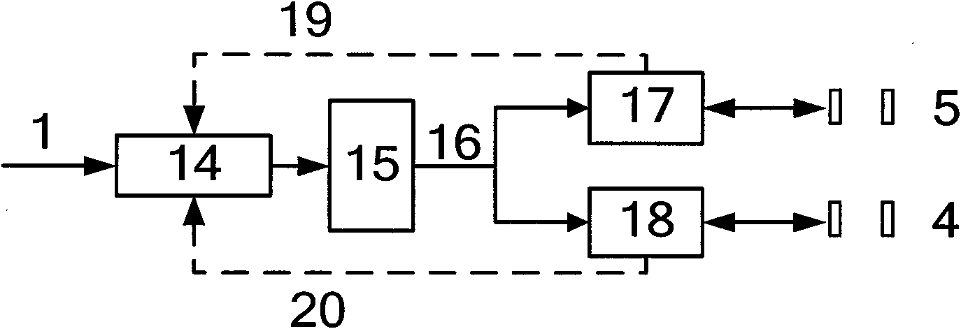
[0039] A high-precision and remote-controllable optical path switching method, the online monitoring and switching unit exchanges information with the remote console through Ethernet or GPRS, uses the main and auxiliary optical fiber lines to transmit optical signals, and monitors the optical signal power and communicates with the device. Compared with the fixed switching threshold to determine the switching gate of the optical path, such as Figure 4 As shown, the steps are as follows:

[0040] (1) Initialization, including online monitoring and switching unit reset, communication control unit reset, optical switch gating the main optical path, clearing the buffer area;

[0041] (2), online monitoring and switching unit control chip detects whether there is a serial port command, if there is, then go to step (8), otherwise go to the next step;

[0042] (3) Monitor the optical power of the main and auxiliary optical fiber lines in real time, and transmit the optical power val...

Embodiment 2

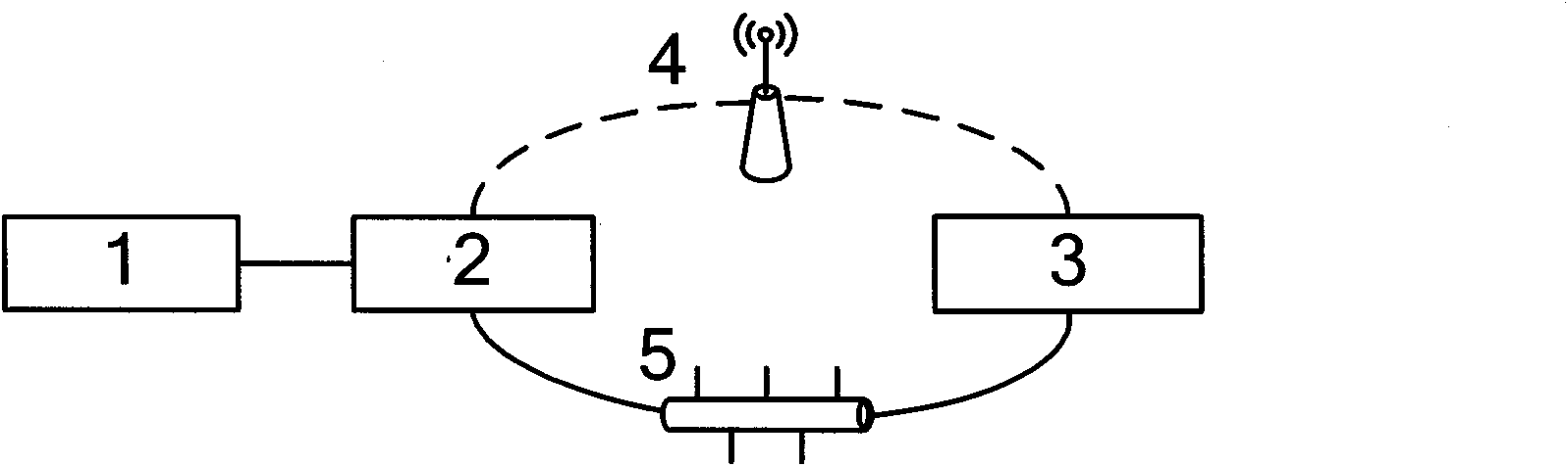
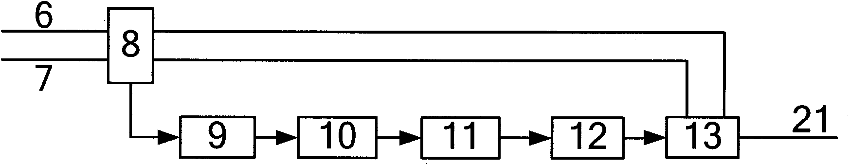
[0054] A high-precision remote control optical path switching system for the above method, such as Figure 1-3 As shown, it consists of an online monitoring and switching unit 1, a communication control unit 2 and a remote console 3, and is characterized in that the online monitoring and switching unit 1 consists of two groups of optical devices 8, photodiodes 9, logarithmic amplifiers 10, A / D The converter 11, the optical switch 13 and the control chip 12 are composed; two groups of optical devices 8 are located in front of the photodiode 9 to respectively receive the optical signals from the main optical fiber 6 and the auxiliary optical fiber 7 and decompose them into two signals according to the splitting ratio of 3:97 , wherein the optical signal with more light splitting is sent to the optical switch 13 for gating the optical path, and the optical signal with less light splitting is sent to the photodiode 9; the photodiode 9 is connected to the logarithmic amplifier 10 an...


PUM


Abstract

The invention discloses a high-precision remote optical path switch scheme and a system, belonging to the technical filed of optical networking communication. An on-line monitoring and switching unit exchanges information with a remote console by Ethernet or a GPRS mode, a main optical-fibre circuit and an auxiliary optical-fibre circuit are utilized to transmit optical signals, and optical signal power is monitored and compared with a set switching threshold to determine whether the optical path switching is gated; the system comprises the on-line monitoring and switching unit, a communication control unit and the like; the on-line monitoring and switching unit is composed of an optical splitter, a photodiode, a logarithm amplifier, an A/D converter, an optical switch and a control chip; and by introducing the logarithm amplifier, the accuracy of the optical power acquisition value of the traditional fibre is effectively improved, and the problem that the precision is difficult to be accurately measured due to larger attenuate generated after long distance transmission of an optical fibre trunk network is improved, thereby ensuring more accurate and reliable optical path switch in traditional optical path protection. In addition, after the communication control unit is introduced, remote centralized management on an optical path protection module is realized.

Description

Technical field [0001] The invention relates to the technical field of optical network communication, in particular to a high-precision remote control optical path switching method and system. Background technique [0002] Optical fiber is widely used as a large-capacity information medium, but its flexibility is poor and the process radius is small, and various factors lead to its poor reliability. Currently, 1:1 and 1+1 optical protection mechanisms are mostly used in optical transmission. The principles of the two technical solutions are relatively sufficient, but both have disadvantages such as incompleteness. [0003] The traditional 1:1 optical protection mechanism switches the optical switch at the sending end and the receiving end at the same time to gate the same optical path, which has disadvantages such as difficulty in synchronization. The 1+1 optical protection mechanism transmits the optical signal to the main and auxiliary optical paths at the sending end ac...

Claims


Application Information

Patent Timeline
Patent Type & Authority Applications(China)
IPC IPC(8): H04B10/12H04B10/08H04B10/03H04B10/07
Inventor 李康李本泰
Owner SHANDONG UNIV
Why Eureka
Try Eureka