Electric vehicle

Active Publication Date: 2014-09-25
TOYOTA JIDOSHA KK
View PDF1 Cites 19 Cited by
  • Summary
  • Abstract
  • Description
  • Claims
  • Application Information

AI Technical Summary

Benefits of technology

[0011]The power feeding path switch may include: a first diode inserted in the second power supply path; a second diode inserted in the third power supply path; and a voltage step-down transformer configured to step down a voltage, which is supplied to the power receiving end of the discharger via the second diode, to a voltage lower than a voltage that is supplied to the power receiving end of the discharger via the first diode. With this configuration, because of interposition of the voltage step-down transformer, the potential of the power receiving end through the third power supply path in which the second diode is inserted is lower than the potential of the power receiving end through the second power supply path in which the first diode is inserted. Therefore, both the first and second power supply paths are electrically connected to the power receiving end in a conductive state where the interrupter is not operating; however, the discharger receives electric power through the second power supply path in which the first diode is inserted due to the potential difference. That is, the discharger receives electric power supplied through the second power supply path including the power supply harness. In contrast to this, in an interrupted state where the interrupter is operating, the discharger receives electric power through the third power supply path in which the second di

Problems solved by technology

Therefore, when there occurs a collision of the electric vehicle, part of the power supply harness may contact a metal portion, such as the body of the vehicle, to cause a ground fault.
The overcurrent protection circuit typically interrupts the powe

Method used


Image

  • Electric vehicle
  • Electric vehicle
  • Electric vehicle

Examples


Embodiment Construction

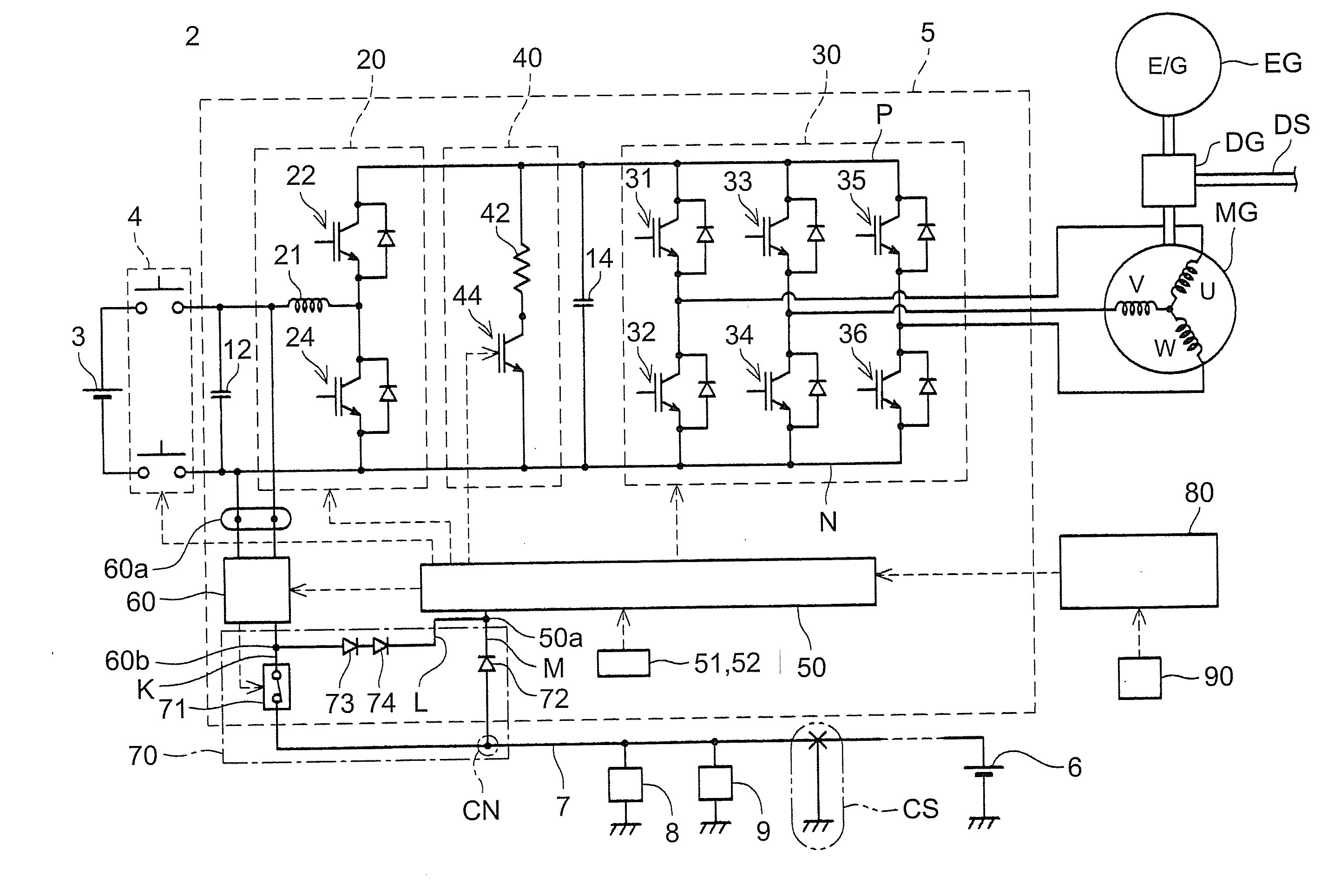
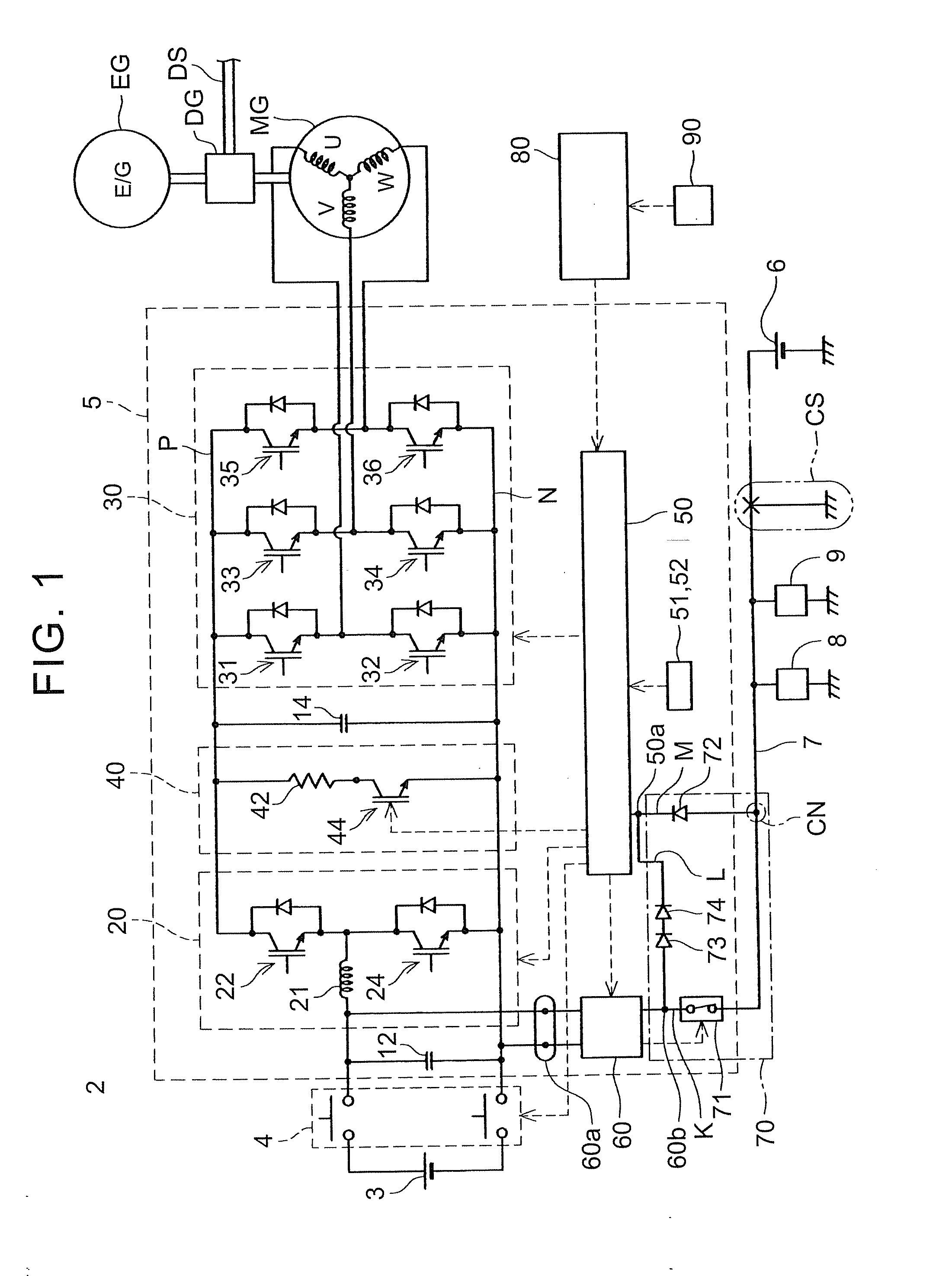
[0020]An electric vehicle according to an embodiment will be described with reference to the accompanying drawings. The electric vehicle according to the embodiment is a hybrid vehicle 2 that includes both a motor and an engine as driving sources. FIG. 1 shows a block diagram of the hybrid vehicle 2. The hybrid vehicle 2 includes the motor MG and the engine EG as the driving sources. The output torque of the motor MG and the output torque of the engine EG are distributed or combined by a power distribution mechanism DG as needed, and are transmitted to an a drive shaft DS (that is, wheels). It should be noted that FIG. 1 only shows components that are required to describe the technique on which the present specification focuses and part of components not regarding the description are not shown in the drawing.

[0021]Electric power for driving the motor MG is supplied from a main battery 3. The output voltage of the main battery 3 is, for example, 300 volts. The hybrid vehicle 2 includ...


PUM


Abstract

An electric vehicle includes: a main battery; an electric power converter configured to convert power to driving power of a drive motor; an auxiliary battery configured to supply power to auxiliaries; a power supply harness connecting the auxiliary battery to the auxiliaries; a step-down converter having an output end connected to the power supply harness, the step-down converter being configured to step down an output voltage of the main battery to the driving voltage of the auxiliaries; an interrupter configured to isolate the step-down converter from the power supply harness at the time when a predetermined specific abnormality has been detected; and a discharger configured to discharge a capacitor incorporated in the electric power converter, the discharger being configured to operate by receiving electric power supplied from a first power supply path which connects the output end of the step-down converter to the interrupter.

Description

[0001]INCORPORATION BY REFERENCE[0002]The disclosure of Japanese Patent Application No. 2013-058265 filed on Mar. 21, 2013 including the specification, drawings and abstract is incorporated herein by reference in its entirety.BACKGROUND OF THE INVENTION[0003]1. Field of the Invention[0004]The invention relates to an electric vehicle. Specifically, the invention relates to an electric vehicle that includes a discharger for discharging a capacitor installed in an electric power converter. The “electric vehicle” according to the invention also includes a fuel-cell vehicle and a hybrid vehicle that includes both a drive motor and an engine.[0005]2. Description of Related Art[0006]A drive motor of an electric vehicle generally has a rated output that reaches several tens of kilowatts. Therefore, large current flows through an electric power converter that supplies driving power to the motor. The electric power converter is typically an inverter that converts direct-current power to alter...

Claims


Application Information

Patent Timeline
IPC IPC(8): H02H7/122B60L11/18
CPCB60L11/1803H02H7/1222B60L1/00H02H3/087H02H7/1213B60L58/18Y02T10/70H02M1/322B60L50/51
Inventor SUGIURA, MASANORI
Owner TOYOTA JIDOSHA KK
Why Eureka
Try Eureka