Flying Toy Figure

a flying toy and toy technology, applied in the field of remote control flying toys, can solve the problems of flying toys that are difficult to control and maneuver during flight, and the toy to crash, and achieve the effects of greater steering and control, greater thrust, and greater control and maneuverability of the figure during fligh

Inactive Publication Date: 2013-10-03
TANOUS WORKS
View PDF5 Cites 0 Cited by
  • Summary
  • Abstract
  • Description
  • Claims
  • Application Information

AI Technical Summary

Benefits of technology

[0009]During flight operation, the propulsion units are independently driven to promote a greater degree of steering and control by the user. The user uses a wireless control device to send a signal to the receiver of the control system to allocate more power to one of the two propulsion units, thereby creating greater thrust on one side of the body, which forces the flying toy figure to turn to in the opposite direction. Since the head and steering bar unit is attached to the body by a flexible support member, the thrust differential between the propulsion units causes the head to move in a yawing motion relative to the body.
[0010]In a common embodiment of the flying toy figure, the control system is mounted to the head, moving weight to the head portion of the flying toy figure. During the yawing motion, the center of gravity of the head moves to the right or left of the longitudinal axis of the figure, thereby causing the figure to bank while turning. The banking motion promotes greater control and maneuverability of the figure during flight.

Problems solved by technology

As a result, these flying toys can be difficult to control and maneuver during flight.
With this loss of control, these toys often fly out of the range of the radio controller, causing the toy to crash.

Method used


Image

  • Flying Toy Figure
  • Flying Toy Figure
  • Flying Toy Figure

Examples


Embodiment Construction

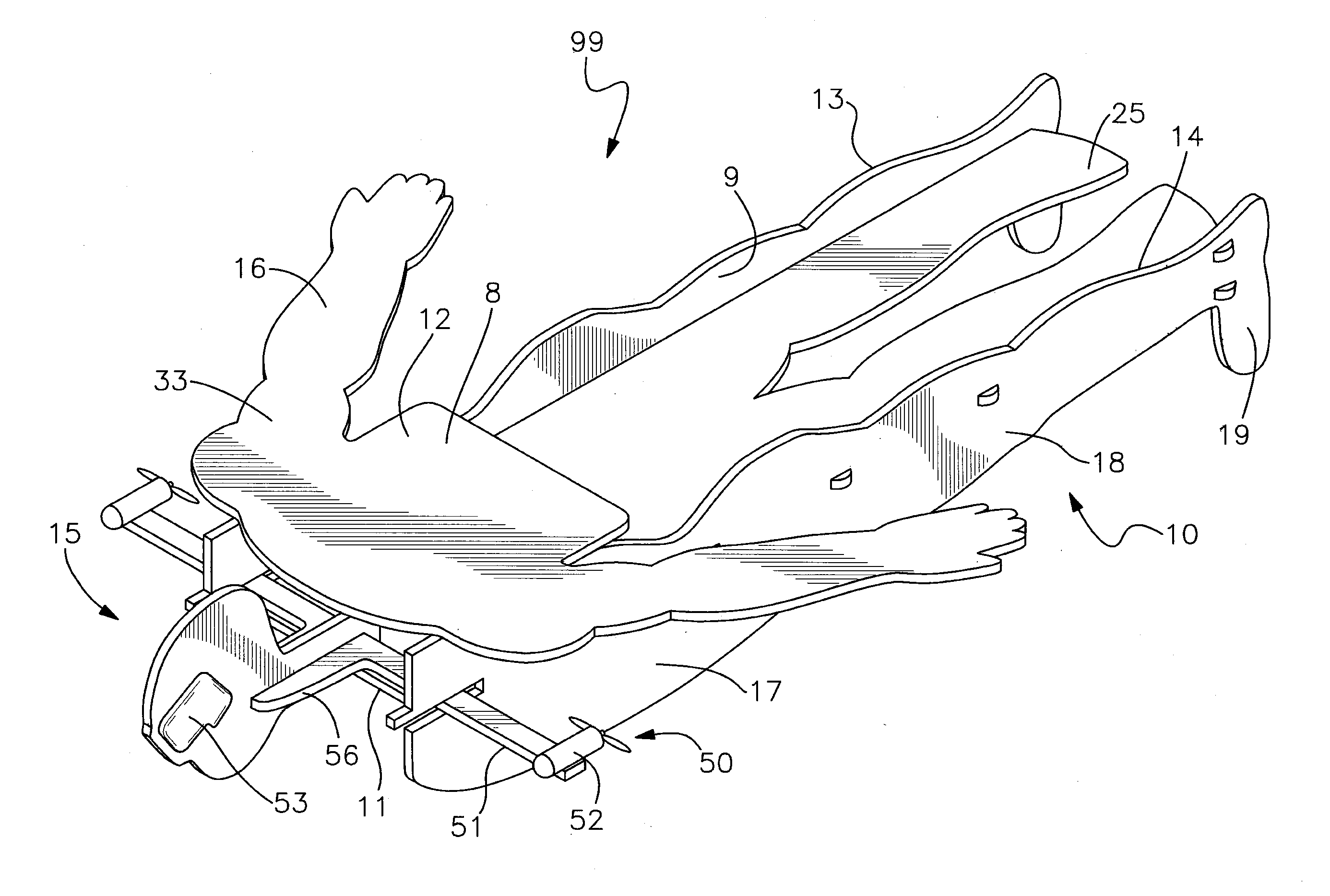
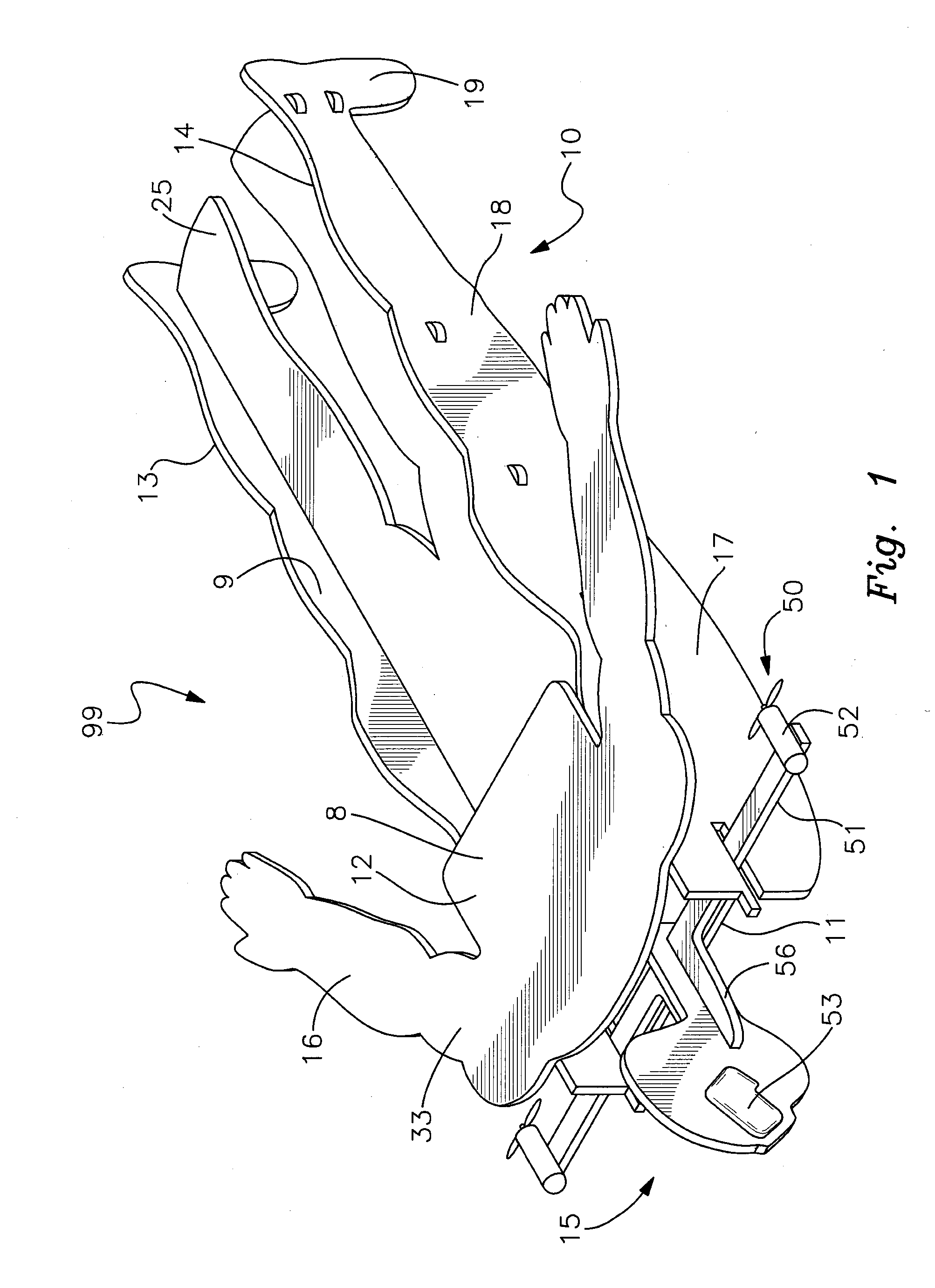
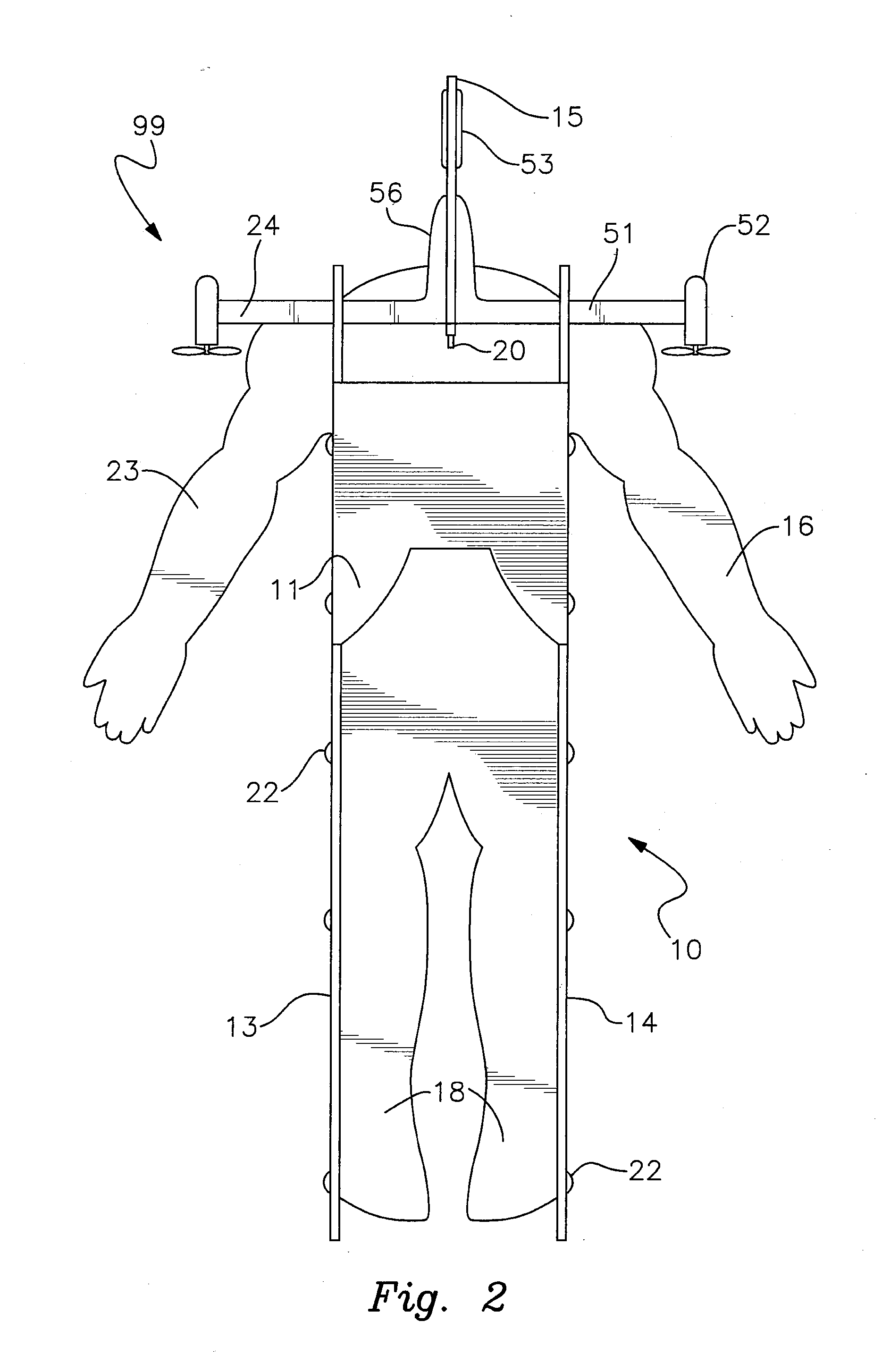
[0021]With reference to the drawings, the invention will now be described with regard for the best mode and the preferred embodiment. In general, the device is a remote controlled, flying toy figure having a head, a body in the shape of a recognizable figure, a propulsion system, and a control system. The embodiments disclosed herein are meant for illustration and not limitation of the invention. An ordinary practitioner will understand that it is possible to create many variations of the following embodiments without undue experimentation.

[0022]The flying toy FIG. 99 is generally controlled by a wireless control device 5 having a transmitter to transmit an electronic signal to the control system 53 of the flying toy FIG. 99. The control system 99 controls the propulsion system 50 on the flying toy FIG. 99 to produce a gliding form of flight, as discussed below. As used herein, the terms “right,”“left,”“forward,”“rearward,”“top,”“bottom,” and similar directional terms refer to orien...


PUM


Abstract

A remote controlled flying toy figure has a thrust-powered, weight shifting rudder head. The flying toy figure comprises a head, a body, a propulsion system, and a control system. The head is attached to the body by a flexible support member, making the head securely fixed in flexible relation to the body, thus permitting a yawing motion of the head relative to the body. The propulsion system comprises two independently operable motorized propellers, each of which is attached to opposite ends of a steering bar. The steering bar and head form an integral steering unit. Increasing the thrust from one of the propellers causes the figure to turn in the opposite direction. This increased thrust causes the steering bar to yaw, which moves the center of gravity of the head to the opposite side of the center line of the body, which causes the figure to bank towards the turn.

Description

CROSS-REFERENCE TO RELATED APPLICATION[0001]This application claims priority to U.S. Provisional Patent Application Ser. No. 61 / 649,893, filed on May 21, 2012, the entire contents of which are incorporated herein by this reference.BACKGROUND OF THE INVENTION[0002]1. Field of the Invention[0003]The present invention relates generally to the field of remote controlled flying toys, and more particularly, to a control and steering system for flying toy figures.[0004]2. Description of Related Art[0005]Past flying toy figures are driven by a single propeller, or by two propellers in fixed relation to the body of the figure. As a result, these flying toys can be difficult to control and maneuver during flight. With this loss of control, these toys often fly out of the range of the radio controller, causing the toy to crash.[0006]The present invention seeks to overcome these problems by providing a steering and propulsion system that is retained in flexible relation to the main body of the ...

Claims


Application Information

Patent Timeline
Patent Type & Authority Applications(United States)
IPC IPC(8): A63H27/00
CPCA63H30/04A63H27/00
Inventor TANOUS, GREGORY DAVID
Owner TANOUS WORKS
Why Eureka
Try Eureka