System and method for implementing force field deterrent for robot

a technology of force field and robot, applied in the field of system and method for implementing force field deterrent for robot, can solve the problem of inconvenient removal of all items from the area in which the robot is located

Active Publication Date: 2013-10-03
IROBOT CORP
View PDF2 Cites 52 Cited by
  • Summary
  • Abstract
  • Description
  • Claims
  • Application Information

AI Technical Summary

Problems solved by technology

However, even when robots are restricted to a bounded area, it is often inconvenient to remove all items from an area in which the robot is performing tasks.

Method used


Image

  • System and method for implementing force field deterrent for robot
  • System and method for implementing force field deterrent for robot
  • System and method for implementing force field deterrent for robot

Examples


Embodiment Construction

[0025]Reference will now be made in detail to exemplary embodiments of the present teachings, examples of which are illustrated in the accompanying drawings. Wherever possible, the same reference numbers will be used throughout the drawings to refer to the same or like parts.

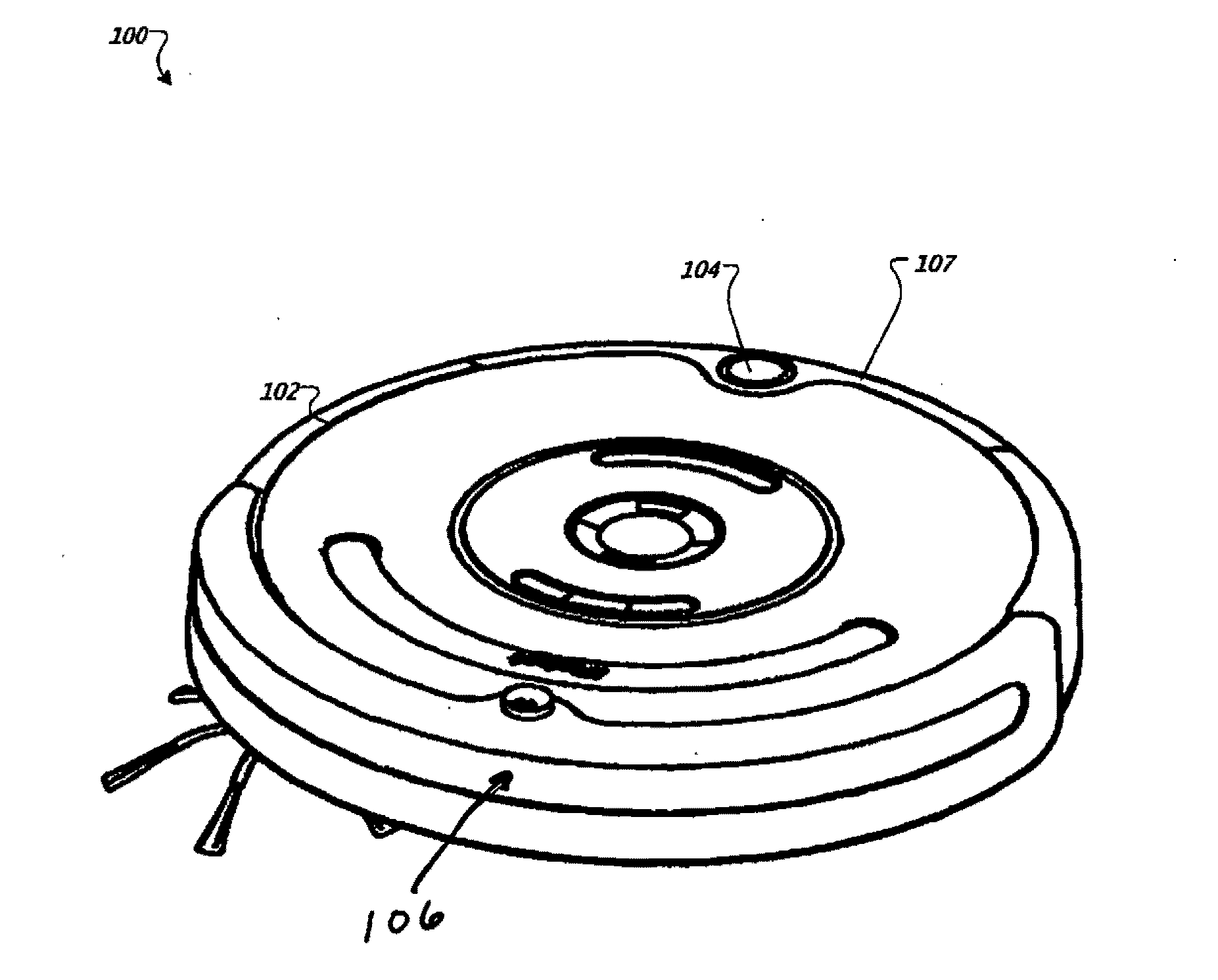
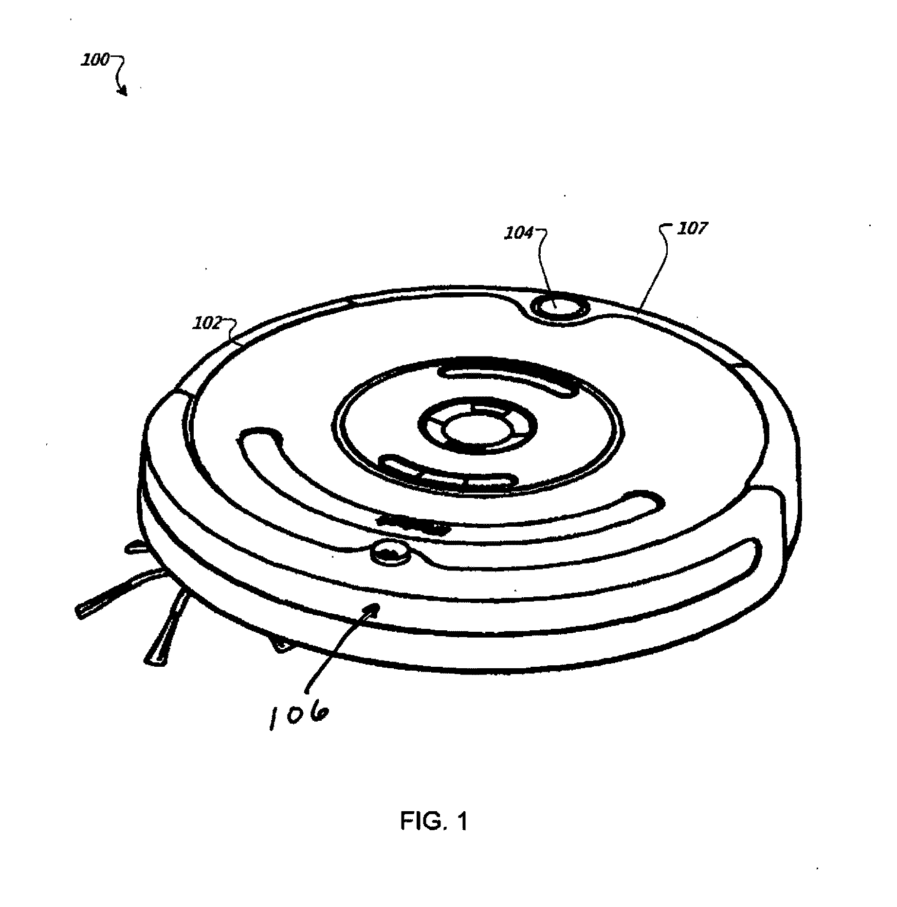
[0026]FIG. 1 shows an above-perspective view of an autonomous coverage robot 100. The robot 100 has a chassis 102, a controller (not shown), an omni-directional receiver 104, and a directional receiver 106. Chassis 102 has a forward drive direction and carries the controller and the receivers 104 and 106 on a bumper 107. Receivers 104 and 106 provide navigation information to the controller. Using input from receivers 104 and 106, the controller generates commands to be carried out by the robot 100. As a result, the robot 100 is capable of cleaning floors in an autonomous fashion.

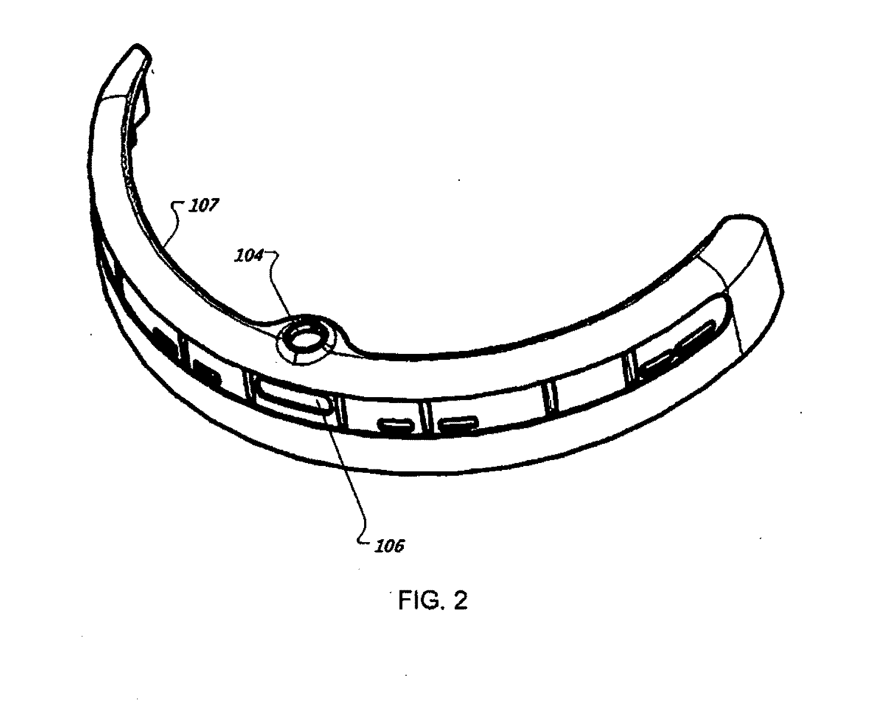
[0027]FIG. 2 illustrates the positions of omni-directional receiver 104 and directional receiver 106 on the bumper 107 of the robot 10...


PUM


Abstract

A robot navigation system includes a robot, a navigation beacon, and a cover structure. The robot includes a chassis, an omni-directional receiver, and at least one directional receiver. The navigation beacon includes an omni-directional infrared emitter and at least one directional infrared emitter. The cover structure is configured to block infrared transmissions between the at least one directional infrared emitter and the directional receiver while simultaneously permitting transmissions between the omni-directional infrared emitter and the omni-directional receiver. The cover structure may be made of a black silicone material.

Description

INTRODUCTION[0001]The present teachings relate to robots, and more particularly to a system and method for implementing a force field to deter autonomous robots.BACKGROUND[0002]Autonomous robots are robots which can perform desired tasks in unstructured environments without continuous human guidance. Many kinds of robots are autonomous to some degree. Different robots can be autonomous in different ways. An autonomous coverage robot traverses a work surface without continuous human guidance to perform one or more tasks. In the field of home, office and / or consumer-oriented robotics, mobile robots that perform household functions such as vacuum cleaning, floor washing, patrolling, lawn cutting and other such tasks have been widely adopted.[0003]Navigation beacons are used to bound an area in which the robot operates. Bounding an area may be done, for example, to restrict a robot from entering or leaving an area. However, even when robots are restricted to a bounded area, it is often ...

Claims


Application Information

Patent Timeline
Patent Type & Authority Applications(United States)
IPC IPC(8): G05D1/02F21V9/04
CPCG05D1/0272A47L2201/04G05D2201/0215G05D1/0227G05D1/0234G05D1/0225
Inventor BURNETT, SCOTT THOMASMAROON, JARED RANDALL
Owner IROBOT CORP
Why Eureka
Try Eureka