High temperature fuel manifold for gas turbine engines

a gas turbine engine and high temperature technology, applied in the field of fluid distribution manifolds, can solve the problems of compromising the hose of the fuel manifold, putting a tremendous thermal strain on the engine components, and being exposed to flames

Active Publication Date: 2013-10-10
COLLINS ENGINE NOZZLES INC
View PDF7 Cites 3 Cited by
  • Summary
  • Abstract
  • Description
  • Claims
  • Application Information

AI Technical Summary

Benefits of technology

[0014]In another aspect, a liner defining an internal fluid passage therethrough fluidly connects a pair of hose fitting inserts. The flexible thermal shield is outboard of the liner, and the insulation space is defined between the liner and the flexible thermal shield. The outer collar can include fitting threads engaged with threads on one of the hose fitting inserts. The fitting threads of the outer collar can be structurally ovalized relative to the threads of the hose fitting insert engaged thereto to prevent unthreading of the collar.
[0015]In accordance with certain embodiments, a lock wire can connect the outer collar to the hose fitting insert engaged t

Problems solved by technology

The high operating temperatures in modern gas turbine engines put a tremendous thermal strain on engine components associated with the combustor casing.
Prior art designs of this type have certain disadvantages such as susceptibility to vibration and fatigue.
However, today's high performance gas turbine engines have air temperatures outside the engine case that far exceed that standard.
Expos

Method used


Image

  • High temperature fuel manifold for gas turbine engines
  • High temperature fuel manifold for gas turbine engines
  • High temperature fuel manifold for gas turbine engines

Examples


Embodiment Construction

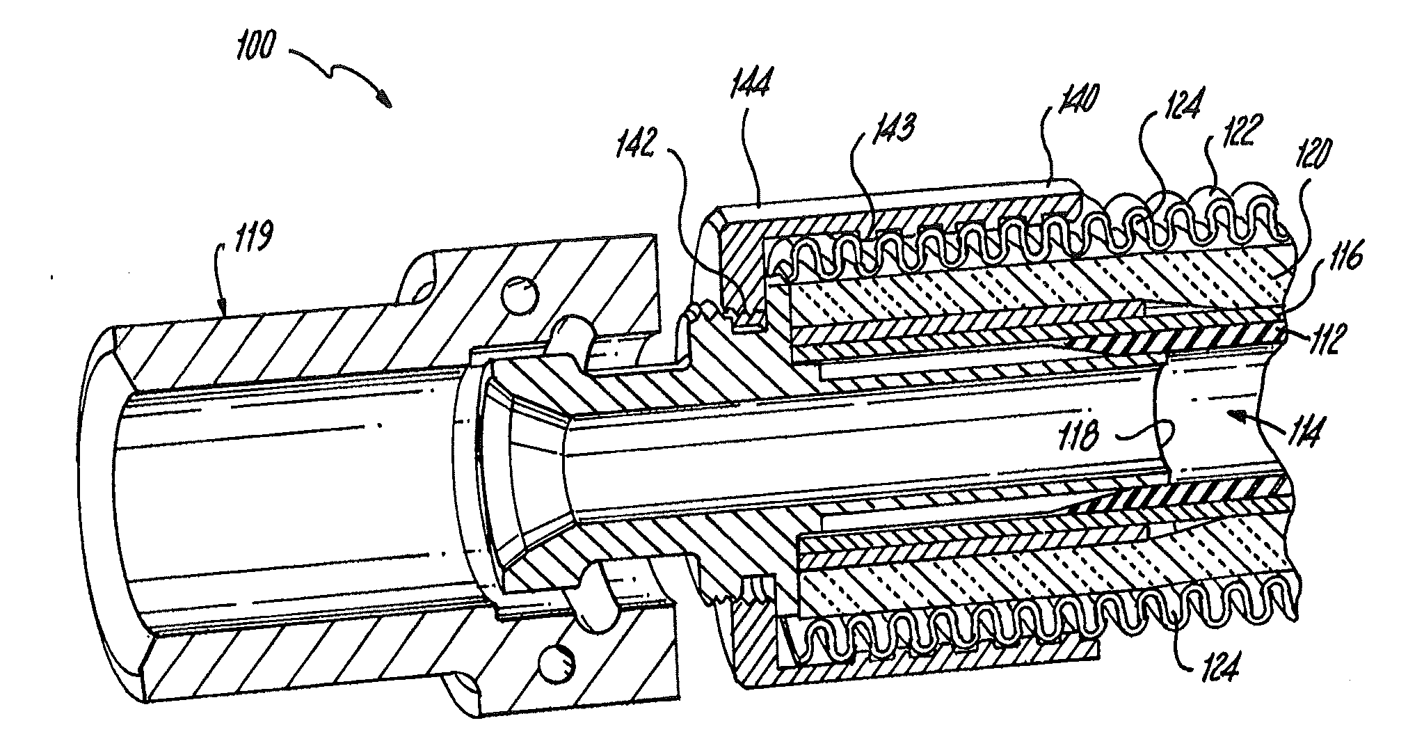
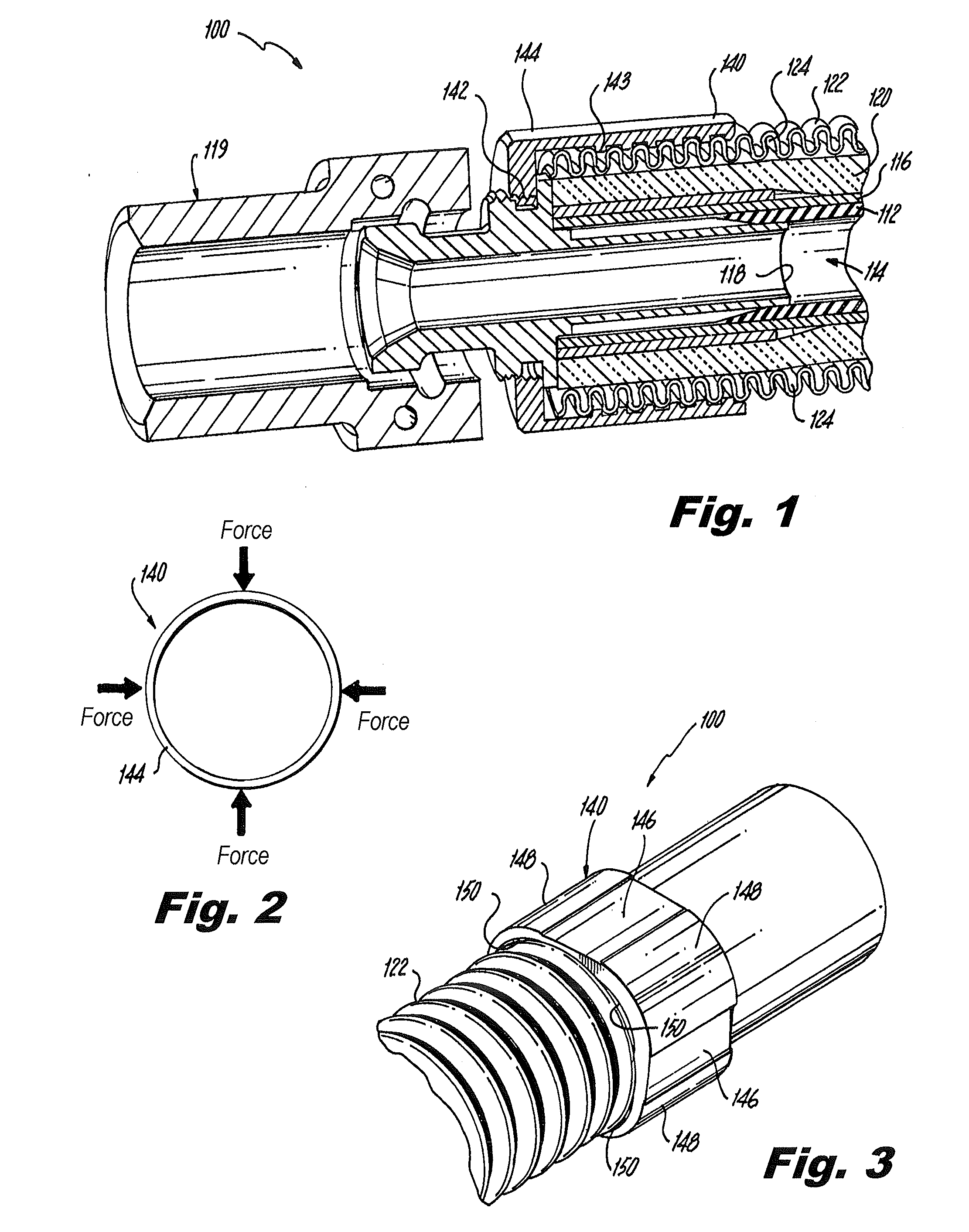
[0029]Reference will now be made to the drawings wherein like reference numerals identify similar structural features or aspects of the subject invention. For purposes of explanation and illustration, and not limitation, a partial view of an exemplary embodiment of a segment for a fluid manifold is shown in FIG. 1 and is designated generally by reference character 100. Other embodiments of segments for fluid manifolds, or aspects thereof, are provided in FIGS. 2-3, as will be described. The systems and methods of the invention can be used to improve high temperature operation and flame resistance, for example in fuel manifolds of gas turbine engines.

[0030]Manifold segment 100 includes a fuel liner 112 with a fuel passage 114 therethrough. Liner 112 fluidly connects a pair of hose fitting insert 118, each having a nut 119 for connection to a manifold. Wire braid layer 116 surrounds liner 112, and a fire sleeve 120 surrounds wire braid layer 116. Fire sleeve 120 can include a layer of...


PUM


Abstract

A segment of a fluid manifold includes a flexible thermal shield with an insulation space defined inboard of the thermal shield to provide thermal isolation from conditions external to the thermal shield. The thermal shield includes a helically corrugated metal tube having opposed first and second ends. An outer collar is threaded to an end of the helically corrugated metal tube. The outer collar includes a crimped portion and an uncrimped portion. The uncrimped portion is spaced apart from the corrugated helical metal tube more than the crimped portion to define a vent between the outer collar and the corrugated helical metal tube in venting communication with the insulation space to vent hot gases.

Description

CROSS-REFERENCE TO RELATED APPLICATIONS[0001]This application is a continuation in part of U.S. patent application Ser. No. 12 / 889,275 filed Sep. 23, 2010, which is incorporated by reference herein in its entirety.BACKGROUND OF THE INVENTION[0002]1. Field of the Invention[0003]The present invention relates to fluid distribution manifolds, and more particularly to high temperature fuel manifolds for gas turbine engines.[0004]2. Description of Related Art[0005]The fuel manifold system of a gas turbine engine distributes fuel from a fuel control system to a plurality of fuel injectors mounted on the engine case. The fuel injectors are configured to issue atomized fuel into the combustor of the engine. It is well known that combustor inlet air temperatures can be extremely high (e.g., 1300° F., 704.4° C.), and the combustion of fuel drives temperatures even higher. High combustor temperatures are necessary in order to fully ignite the fuel and to derive the maximum amount of energy avai...

Claims


Application Information

Patent Timeline
IPC IPC(8): F02C7/22
CPCF02C7/24F02C7/222F02C7/25F05D2250/61
Inventor BLEEKER, DANIEL EDWARD
Owner COLLINS ENGINE NOZZLES INC
Why Eureka
Try Eureka