Transparent Micropatterned RFID Antenna and Articles Incorporating Same

a technology of transparent micro-patterned rfid antennas and antennas, which is applied in the structural form of resonant antennas, instruments, radiating elements, etc., can solve the problems of not being useful in other rfid devices, unsuitable conductors for antennas in rfid applications, and unknown and uncertain suitability of conductors for certain specific applications

Inactive Publication Date: 2013-10-10
3M INNOVATIVE PROPERTIES CO
View PDF7 Cites 34 Cited by
  • Summary
  • Abstract
  • Description
  • Claims
  • Application Information

AI Technical Summary

Benefits of technology

[0008]Electrical conductors in the form of a micropatterned conductive material are known. In these constructions, a layer of metal or other suitable electrically conductive material is disposed on an electrically insulating substrate. The metal layer is micropatterned to form a two-dimensional mesh of conductive linear features. Exemplary micropatterned conductors are described in one or more of the following patent documents: PCT Publications WO 2009 / 108765 (Frey et al.), WO 2009 / 108771 (Zu et al.), WO 2009 / 154812 (Frey et al.), and WO 2010 / 099132 (Moran et al.).

Problems solved by technology

Although such patterned conductors can be made to have a low visibility or high transparency by using a pattern that has a large “open area fraction”, the suitability of such conductors for certain specific applications is unknown.
In particular, the suitability of such conductors for use as antennas in RFID applications is unknown and uncertain.
The results of these studies show that such high transparency micropatterned conductors, sometimes also referred to as conductive micropatterns, can be made to be useful in some RFID devices, but are not as useful in other RFID devices.

Method used


Image

  • Transparent Micropatterned RFID Antenna and Articles Incorporating Same
  • Transparent Micropatterned RFID Antenna and Articles Incorporating Same
  • Transparent Micropatterned RFID Antenna and Articles Incorporating Same

Examples


examples 2-45

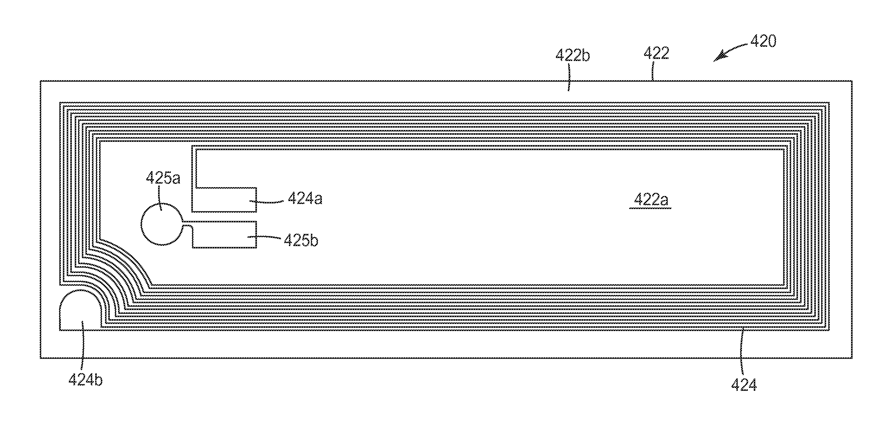
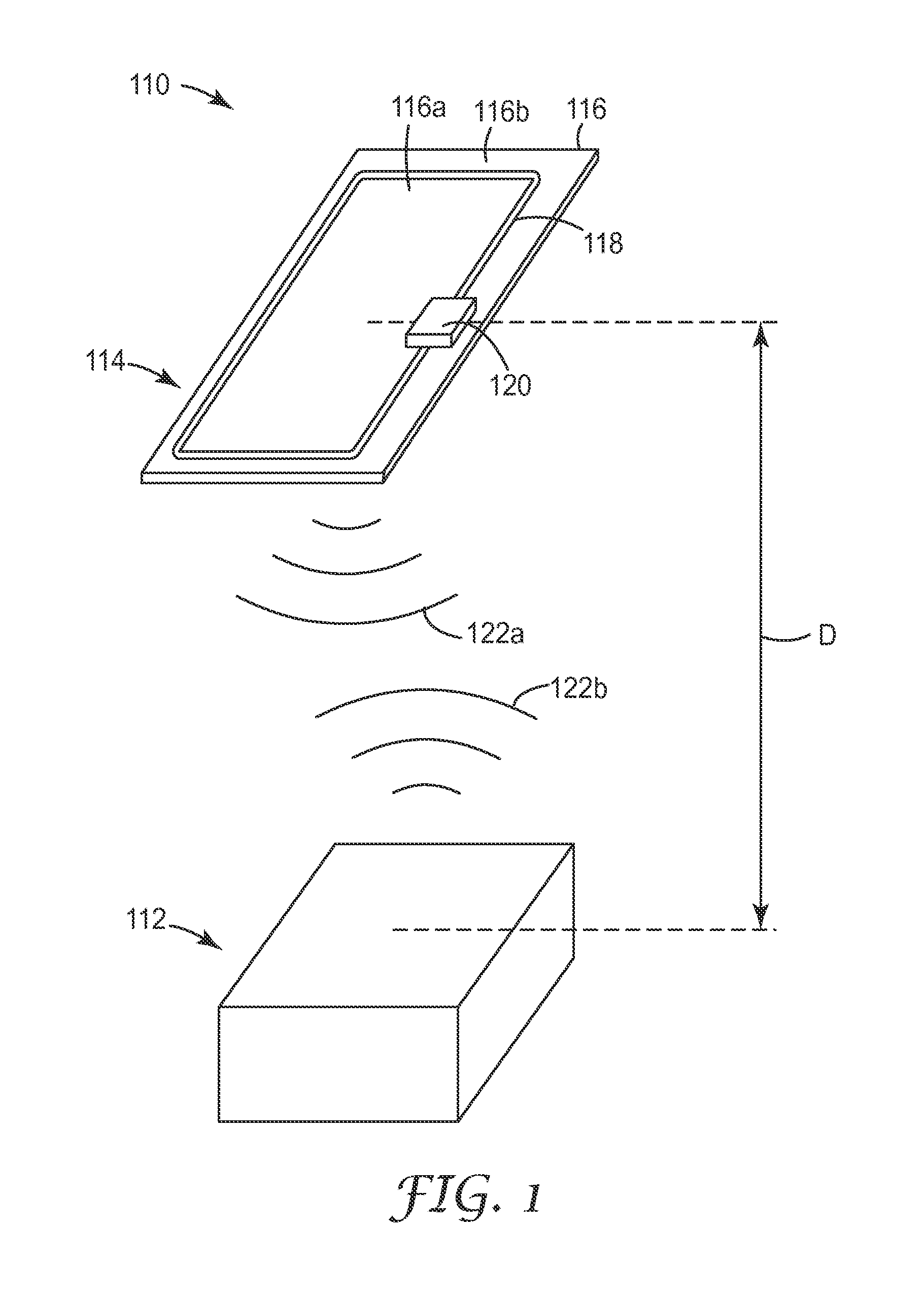
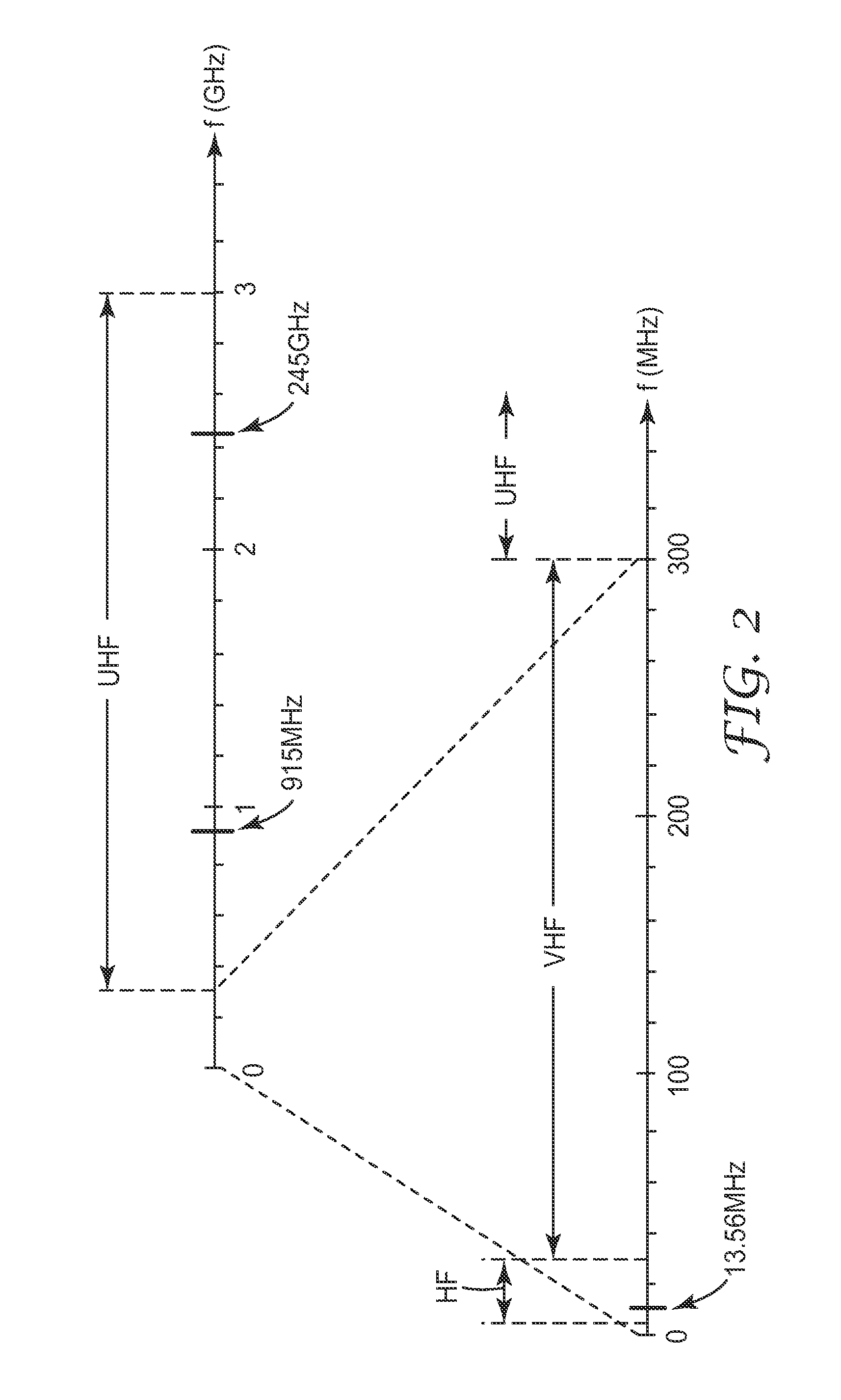
[0095]RFID antennas were fabricated using high transparency micropatterned conductors. A variety of antenna designs were used, including antennas adapted for use at 13.56 MHz and antennas adapted for use at 915 MHz. Different micropatterned conductors were also used, the differences including differences in trace width, trace pitch, trace thickness, and open area fraction. For each RFID antenna, the DC resistance of the antenna was measured with a digital multimeter (Fluke 73III Multimeter, Fluke Corporation, USA), and an RFID integrated circuit was then connected to the antenna. The RFID device so fabricated was then evaluated with a conventional RFID reader to determine if a signal could be observed when the RFID device was positioned directly against the RFID reader. If a signal was observed, the distance between the RFID reader and RFID device was then progressively increased until a signal was no longer observed, that distance being recorded as the value Dmax discussed above in...


PUM

PropertyMeasurementUnit
frequencyaaaaaaaaaa
widthaaaaaaaaaa
thicknessaaaaaaaaaa

Abstract

Antennas suitable for use in RFID devices include an insulating substrate and a first conductive micropattern disposed on or in the substrate, the first conductive micropattern defining a contiguous mesh conductor. The first conductive micropattern forms an antenna responsive to at least a frequency of 915 MHz, and includes interconnected traces having a trace width in a range from 0.5 to 20 microns. Furthermore, the first conductive micropattern is characterized by an open area fraction of at least 80% or 90%. RFID devices include such an antenna and an integrated circuit configured to transmit and receive signals using the antenna. Cards, such as financial transaction cards or identification cards, include such an antenna carried by a card layer.

Description

FIELD OF THE INVENTION[0001]This invention relates generally to radio frequency identification (RFID) devices, with particular application to antennas used in such devices. The invention also relates to associated articles, systems, and methods.BACKGROUND[0002]Radio-Frequency Identification (RFID) technology has become widely used in many industries, including transportation, shipping, manufacturing, waste management, postal tracking, airline baggage reconciliation, and highway toll management. RFID tags and labels are useful for tracking shipments from the supplier to the customer and even through the customer's supply chain.[0003]A typical RFID system includes a plurality of RFID tags or labels, at least one RFID reader or detection system having an antenna for communication with the RFID tags or labels, and a computing device to control the RFID reader. An RFID tag may or may not include a layer of adhesive. An RFID label typically is an RFID tag having a layer of adhesive for at...

Claims


Application Information

Patent Timeline
Patent Type & Authority Applications(United States)
IPC IPC(8): G06K19/077H01Q1/38
CPCH01Q1/2225H01Q1/38G06K19/07783G06K19/07773H01Q7/00C23F1/02G06K19/077
Inventor FREY, MATTHEW H.ZU, LIJUNEGBERT, WILLIAM C.BANERJEE, SWAGATA R.SAINATI, ROBERT A.
Owner 3M INNOVATIVE PROPERTIES CO
Why Eureka
Try Eureka