Method and device for converting firearm with detachable magazine to a firearm with fixed magazine

a technology of semiautomatic firearms and fixed magazines, applied in the field of semiautomatic firearms, can solve the problems of firearms no longer accepting detachable magazines and firearms that cannot accept fixed magazines

Active Publication Date: 2013-10-17
EVOLUSION CONCEPTS INC
View PDF30 Cites 39 Cited by
  • Summary
  • Abstract
  • Description
  • Claims
  • Application Information

AI Technical Summary

Benefits of technology

[0016]In accordance with one aspect of the present invention, a firearm is provided comprising a lower receiver, a magazine catch bar, and an upper tension bar. The magazine catch bar is securely attached to the lower receiver and fits within a recess in the magazine well of the lower receiver. The upper tension bar applies a pressure against the upper receiver of the firearm, sufficient to render the magazine catch bar immovable when the upper receiver and lower receiver of the firearm are firmly attached in a closed position. The magazine catch bar freely moves when the upper receiver and the lower receiver of the firearm are apart and in an open position, permitting the magazine catch bar to lift from the magazine side-locking recess sufficiently to permit a magazine to be removed from the magazine well of the lower receiver when the upper receiver and the lower receiver of the firearm are apart and in an open position. The upper tension bar may contain a set screw permitting a user to adjust the pressure at the point of contact between the upper tension bar and the upper receiver. The upper tension bar and magazine catch bar are attached to the lower receiver by means of a screw which passes through the lower receiver. The upper tension bar and magazine catch bar are positioned on separate sides of the lower receiver.
[0017]In accordance with another aspect of the present invention a firearm subassembly is provided comprising a magazine catch, a magazine catch pivo

Problems solved by technology

The firearm can only accept a fixed magazine when the firearm action is disassembled.
When in

Method used


Image

  • Method and device for converting firearm with detachable magazine to a firearm with fixed magazine
  • Method and device for converting firearm with detachable magazine to a firearm with fixed magazine
  • Method and device for converting firearm with detachable magazine to a firearm with fixed magazine

Examples


Embodiment Construction

[0024]Since the basic firearm is of a well-known type, only those parts of the firearm essential to an understanding of the invention will be described in detail. Although the present invention will be described with reference to the exemplary embodiments shown in the drawings, it should be understood that the present invention can be embodied in many alternate forms or embodiments. In addition, any suitable size, shape or type of elements or materials could be used.

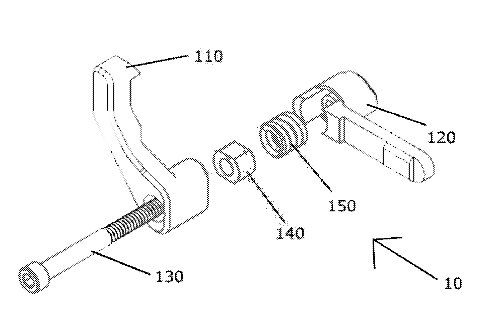
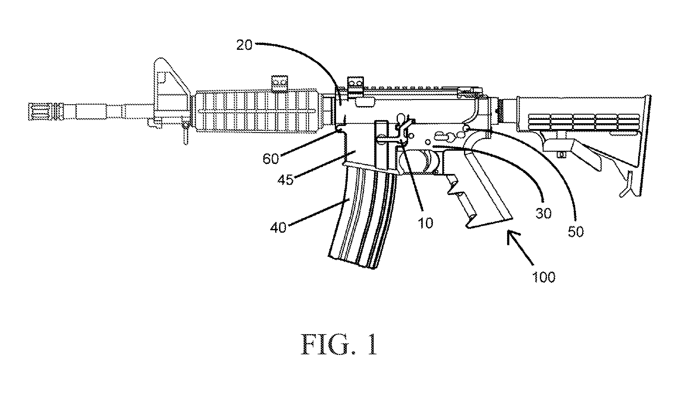
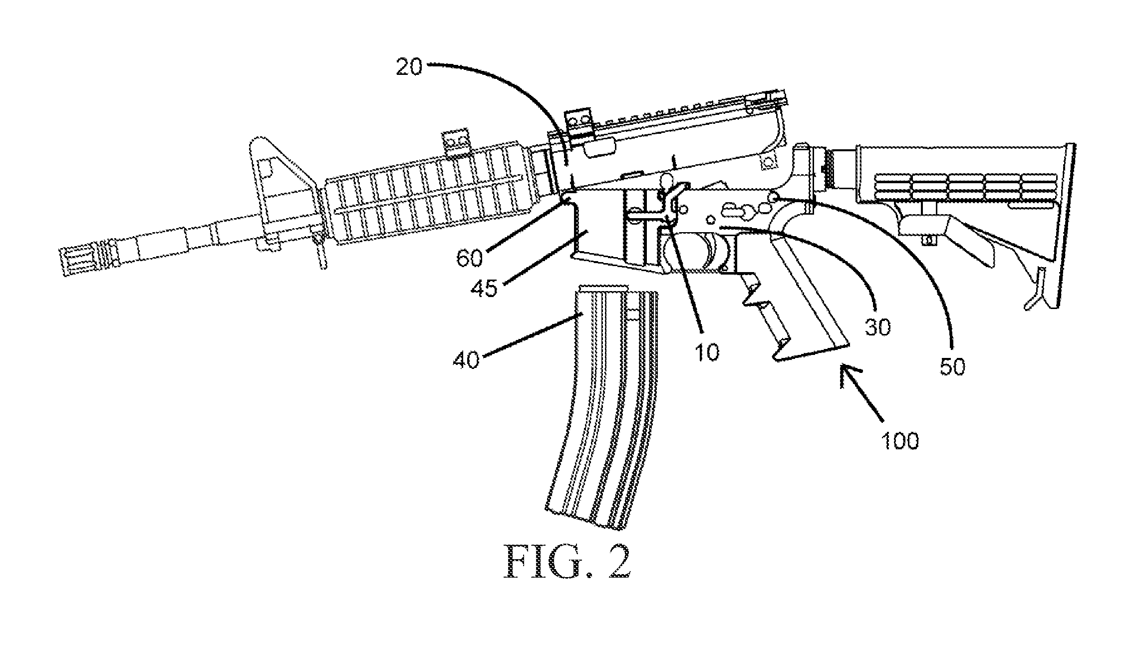
[0025]Referring to FIGS. 1-2 the firearm 100 is comprised of an upper receiver 20 and a lower receiver 30. The lower receiver 30 comprises partially of a magazine well receiver 45 and a rear takedown pin 50. The magazine well receiver 45 is structured to accept a magazine 40 containing rounds of ammunition. As FIG. 2 shows, the lower receiver 30 and upper receiver 20 can scissored open when the rear takedown pin 50 is removed, allowing the upper receiver 20 to be pivoted at the point of the pivot pin 60. FIGS. 1-2 show t...


PUM

PropertyMeasurementUnit
Pressureaaaaaaaaaa
Depthaaaaaaaaaa
Tensionaaaaaaaaaa

Abstract

An accessory which becomes an integral part of a semi-automatic firearm whereby the firearm is converted from one with a detachable magazine into one with a fixed magazine. The device is comprised of an upper tension bar and a magazine catch bar whereby the upper tension bar holds the magazine firmly within the magazine well receiver when the upper tension bar is contacting the upper receiver. When the upper receiver and lower receiver of the firearm are in an open position, the upper tension bar freely moves inward toward the firearm, allowing the magazine catch bar to remove from the magazine well receiver. A user may then remove the magazine from the magazine well receiver and replace it with a new magazine. The user must reattach the upper receiver to the lower receiver before utilizing the firearm.

Description

TECHNICAL FIELD[0001]The invention relates generally to semi-automatic firearms and more specifically to a device and method for converting a semi-automatic firearm with a -detachable magazine to a semi-automatic firearm with a fixed magazine.BACKGROUND OF THE INVENTION[0002]Semi-automatic firearms have been known for a long time. The first semi-automatic rifle was introduced in 1885. The M-16 automatic rifle has been used by the military for years. A civilian version of the M-16 is known as the AR-15 and is a semi-automatic rifle. The AR-15 has been manufactured and sold to civilians for many years. Standard AR-15 semi-automatic rifles are manufactured and distributed with detachable magazines. A detachable magazine allows a user to fire the gun multiple times until all bullets in the magazine have been fired. When the magazine is depleted, the user pushes a magazine release button. This releases the magazine from the rifle. The user may then insert a new magazine and resume firing...

Claims


Application Information

Patent Timeline
IPC IPC(8): F41A9/64
CPCF41A9/64F41A3/66F41A9/65F41A17/38Y10T29/49716
Inventor HARRIS, COURTNEYTHOMAS, SEANBERNARD, ROBERT
Owner EVOLUSION CONCEPTS INC
Why Eureka
Try Eureka