
Hydraulic clutch assembly and method of providing hydraulic fluid to a hydraulic clutch assembly

a technology of hydraulic clutch and hydraulic fluid, which is applied in the direction of fluid-actuated clutches, clutches, non-mechanical actuated clutches, etc., can solve the problem of additional time and fluid needed to refill the hydraulic clutch application chamber, the order of filling is typically not controlled, and the mechanical dump valve is expensiv

Inactive Publication Date: 2013-10-17
HAMILTON SUNDSTRAND CORP
View PDF2 Cites 0 Cited by
  • Summary
  • Abstract
  • Description
  • Claims
  • Application Information

AI Technical Summary

Benefits of technology

This patent describes a hydraulic clutch assembly that includes friction clutch discs that can be engaged or disengaged to transfer rotational energy. The assembly has two toroidal hydraulic chambers that press the clutch discs into engagement. A lubrication circuit supplies hydraulic fluid to the chambers and the clutch discs. The method involves directing hydraulic fluid from a reservoir through the circuit to the chambers, with the hydraulic fluid being directed to the chamber that is relatively filled first. The technical effect of the patent text is to provide a hydraulic clutch assembly with improved fluid distribution and control for effective engagement and disengagement of the clutch discs.

Problems solved by technology

Typically, such clutches implement a costly mechanical dump valve to circumvent the clamp loads and allow springs to retract an applied clutch.
This results in additional time and fluid necessary to refill a hydraulic clutch application chamber and an associated hydraulic circuit for subsequent clutch application.
For clutch assemblies employing multiple hydraulic chambers in an effort to counteract the centrifugal forces generated, hydraulic fluid is directed from a reservoir to the multiple hydraulic chambers, but the order of filling is typically not controlled and one or more of the hydraulic chambers may require a separate and unique filling system.

Method used


Image

  • Hydraulic clutch assembly and method of providing hydraulic fluid to a hydraulic clutch assembly
  • Hydraulic clutch assembly and method of providing hydraulic fluid to a hydraulic clutch assembly
  • Hydraulic clutch assembly and method of providing hydraulic fluid to a hydraulic clutch assembly

Examples


Embodiment Construction

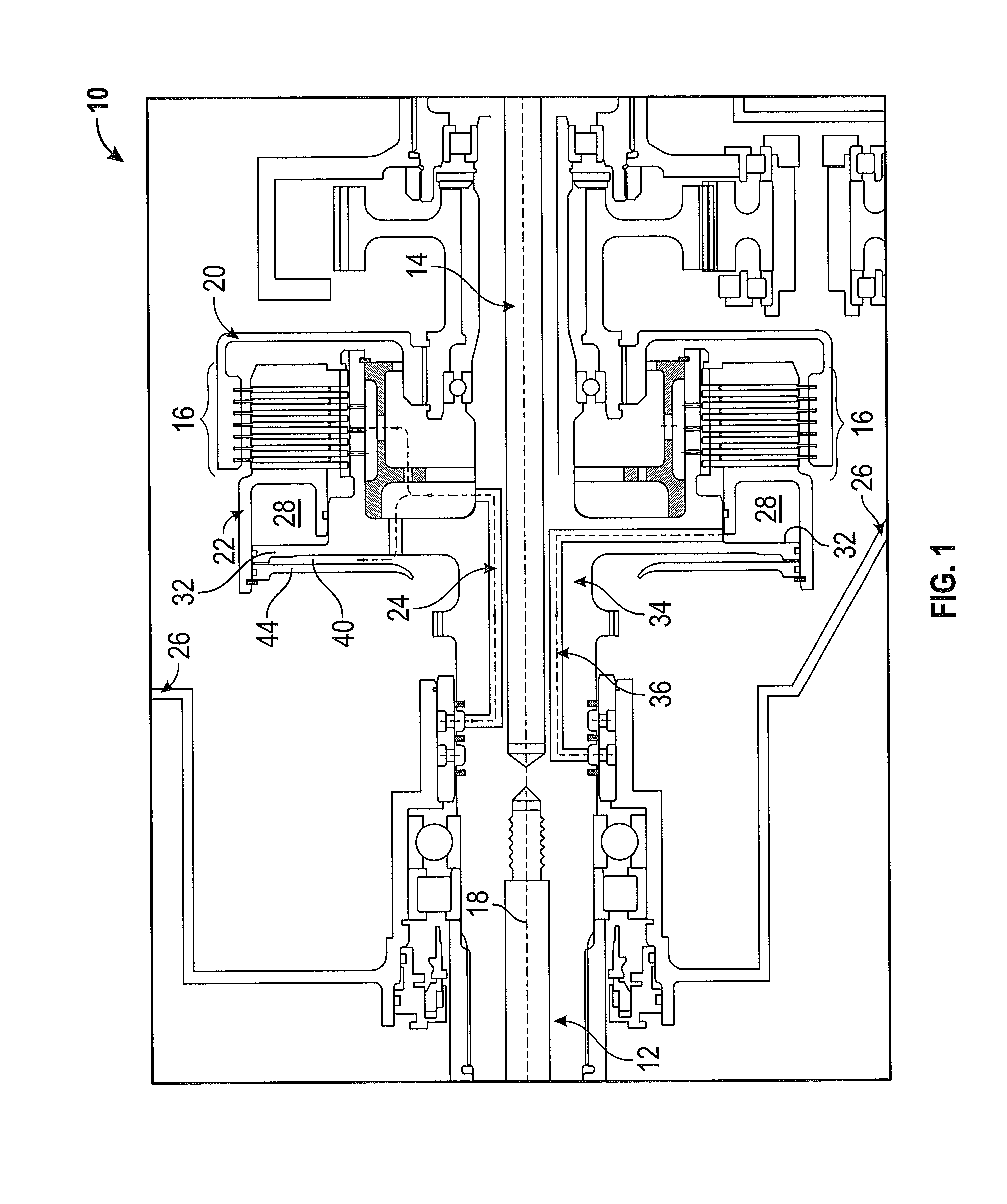
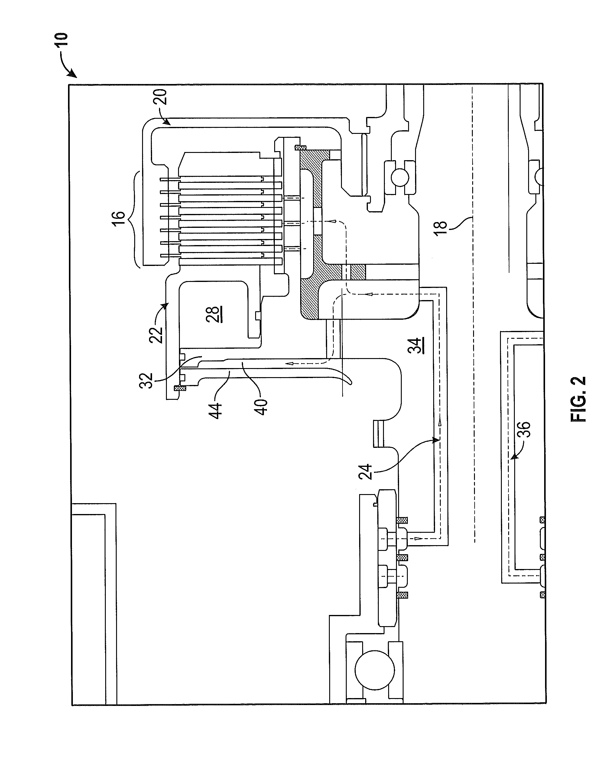
[0009]Referring to FIGS. 1 and 2, a hydraulic clutch assembly (“clutch”) is illustrated and generally referred to with reference numeral 10. The clutch 10 is configured to engage or disengage rotational torque provided from an input portion 12 to an output portion 14 and transfers rotational energy from the input portion 12 to the output portion 14 through a plurality of clutch discs 16. The clutch 10 includes an axis of rotation 18 and a first hub 20 arranged about a second hub 22. Each of the first hub 20 and the second hub 22 may be rotationally symmetric about the axis of rotation 18.

[0010]The second hub 22 may be configured to depress the plurality of clutch discs 16 arranged within the first hub 20 so as to engage the clutch 10, resulting in an engaged condition. The clutch 10 may include a plurality of hydraulic circuits arranged therein to enable depressing the plurality of clutch discs 16. The plurality of clutch discs 16 may be annular, frictional clutch discs of any suita...


PUM


Abstract

A hydraulic clutch assembly includes a plurality of frictional clutch discs moveable between an engaged condition and a disengaged condition, wherein the engaged condition provides a transfer of rotational energy. Also included is a first toroidal hydraulic chamber configured to depress the plurality of frictional clutch discs into the engaged condition. Further included is a second toroidal hydraulic chamber opposing the first toroidal hydraulic chamber, wherein the second toroidal hydraulic chamber is configured to balance centrifugal expansion forces of the first toroidal hydraulic chamber. Yet further included is a lubrication circuit for supplying a hydraulic fluid from a fluid reservoir to the second toroidal hydraulic chamber and the plurality of frictional clutch discs, wherein the second toroidal hydraulic chamber is substantially filled prior to delivery of the hydraulic fluid to the plurality of frictional clutch discs.

Description

BACKGROUND OF THE INVENTION[0001]The present invention relates to hydraulic clutches, and more particularly to hydraulic clutches comprising hydraulic balance chambers, as well as a method of providing hydraulic fluid to hydraulic balance chambers.[0002]High-speed, hydraulically actuated clutches generate large centrifugal pressures. The centrifugal pressure, operating on a clamping piston, generates clamp loads in excess of forces provided by most mechanical springs designed to release a clutch. Therefore, these clamp loads must be overcome to effectively release an applied clutch. Typically, such clutches implement a costly mechanical dump valve to circumvent the clamp loads and allow springs to retract an applied clutch. This results in additional time and fluid necessary to refill a hydraulic clutch application chamber and an associated hydraulic circuit for subsequent clutch application. For clutch assemblies employing multiple hydraulic chambers in an effort to counteract the ...

Claims


Application Information

Patent Timeline
Patent Type & Authority Applications(United States)
IPC IPC(8): F16D25/0635
CPCF16D25/0638F16D25/123F16D48/02F16D2048/029
Inventor WEYL, RAYMOND N.LONG, CHARLES E.
Owner HAMILTON SUNDSTRAND CORP
Features
  • Generate Ideas
  • Intellectual Property
  • Life Sciences
  • Materials
  • Tech Scout
  • Unparalleled Data Quality
  • Higher Quality Content
  • 60% Fewer Hallucinations
Learn More