
Vehicle seat

Active Publication Date: 2013-10-17
TS TECH CO LTD
View PDF4 Cites 36 Cited by
  • Summary
  • Abstract
  • Description
  • Claims
  • Application Information

AI Technical Summary

Benefits of technology

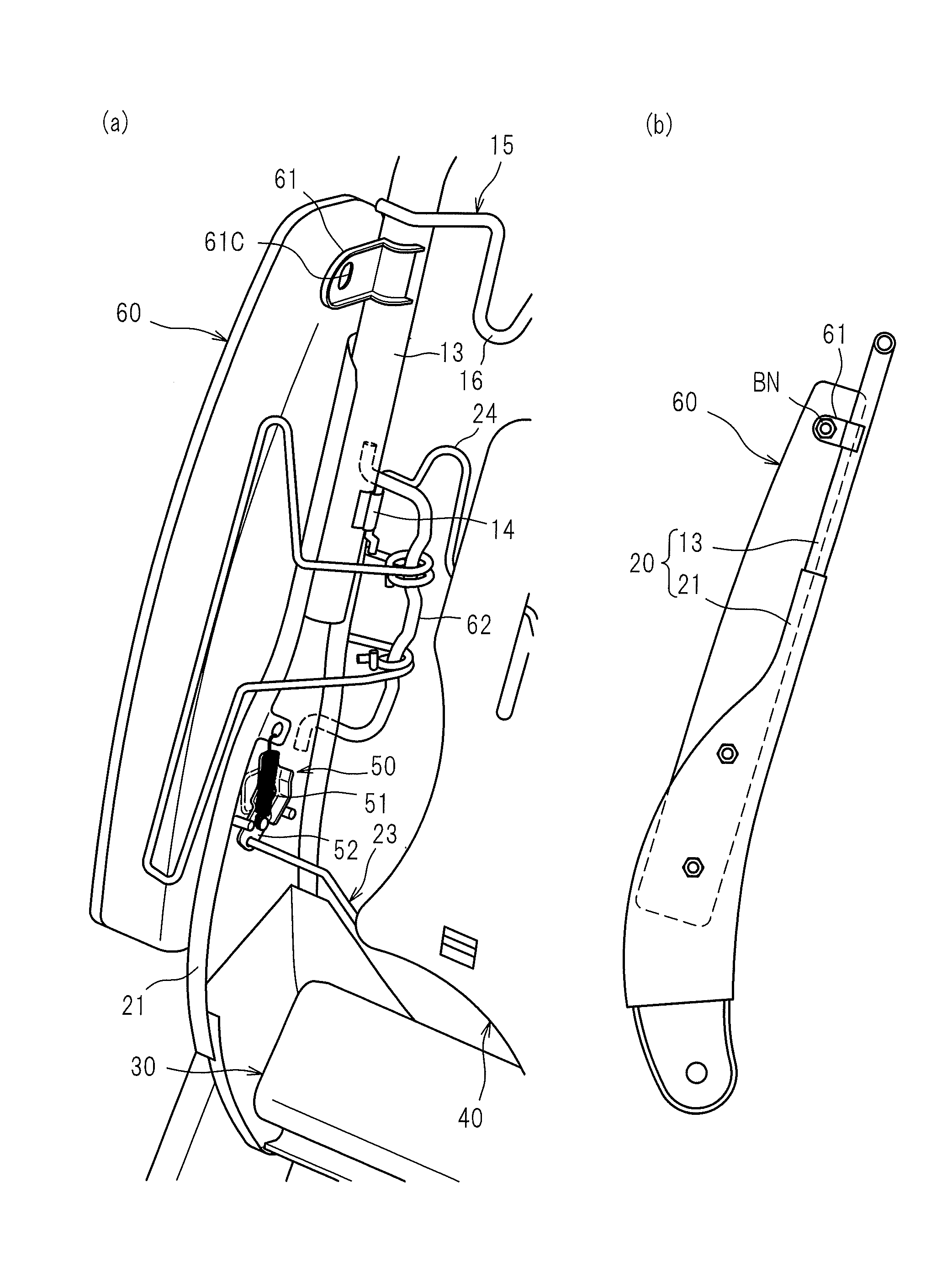
The vehicle seat described in this patent is designed to protect the occupant in a rear-end collision. When the pressure-receiving member moves rearward, the seat back pad moves with them, allowing the upper body of the occupant to subside into the seat back. This reduces tilting-back of the head, absorbing the shock and protecting the occupant from injury. The tuck-in wire is partially positioned along a groove so as to detour around a hole, improving adhesion between the seat back pad and the wire, and reducing damage to the seat back pad. The webbing mounting hardware also suppresses excessive deformation of the side portion towards rearward. Overall, this design helps to ensure safety for the occupant in a collision.

Problems solved by technology

In a rear-end collision of a car that occurs when a rear end of your car is struck by another car or when a rear end of your car which is being reversed strikes another car or a construct, a head of an occupant seated on a seat cushion of a car seat would largely tilt back by inertia, and in reaction thereto, the neck of the occupant would likely be given a large shock.

Method used


Image

  • Vehicle seat
  • Vehicle seat
  • Vehicle seat

Examples


Embodiment Construction

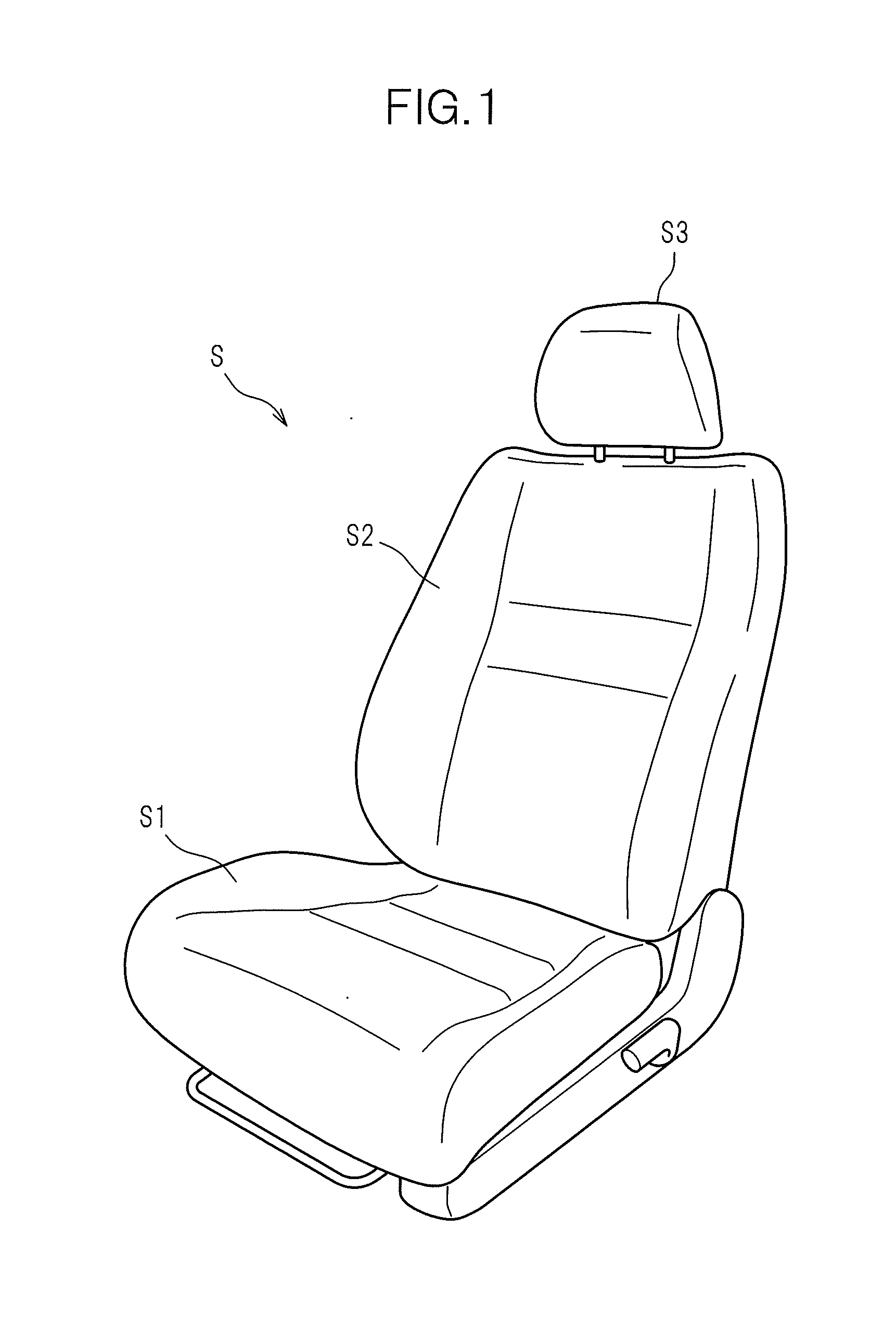
[0051]Hereafter, a description will be given of one embodiment of a vehicle seat according to the present invention with reference made to the accompanying drawings. The vehicle seat according to one embodiment is configured as a car seat S arranged in a location of a driver's seat of an automobile, for example as shown in FIG. 1. This car seat S includes a seat cushion S1, a seat back S2 and a headrest, in which a pad material made of a cushion material such as urethane foam is covered with a skin material such as a synthetic leather or a cloth.

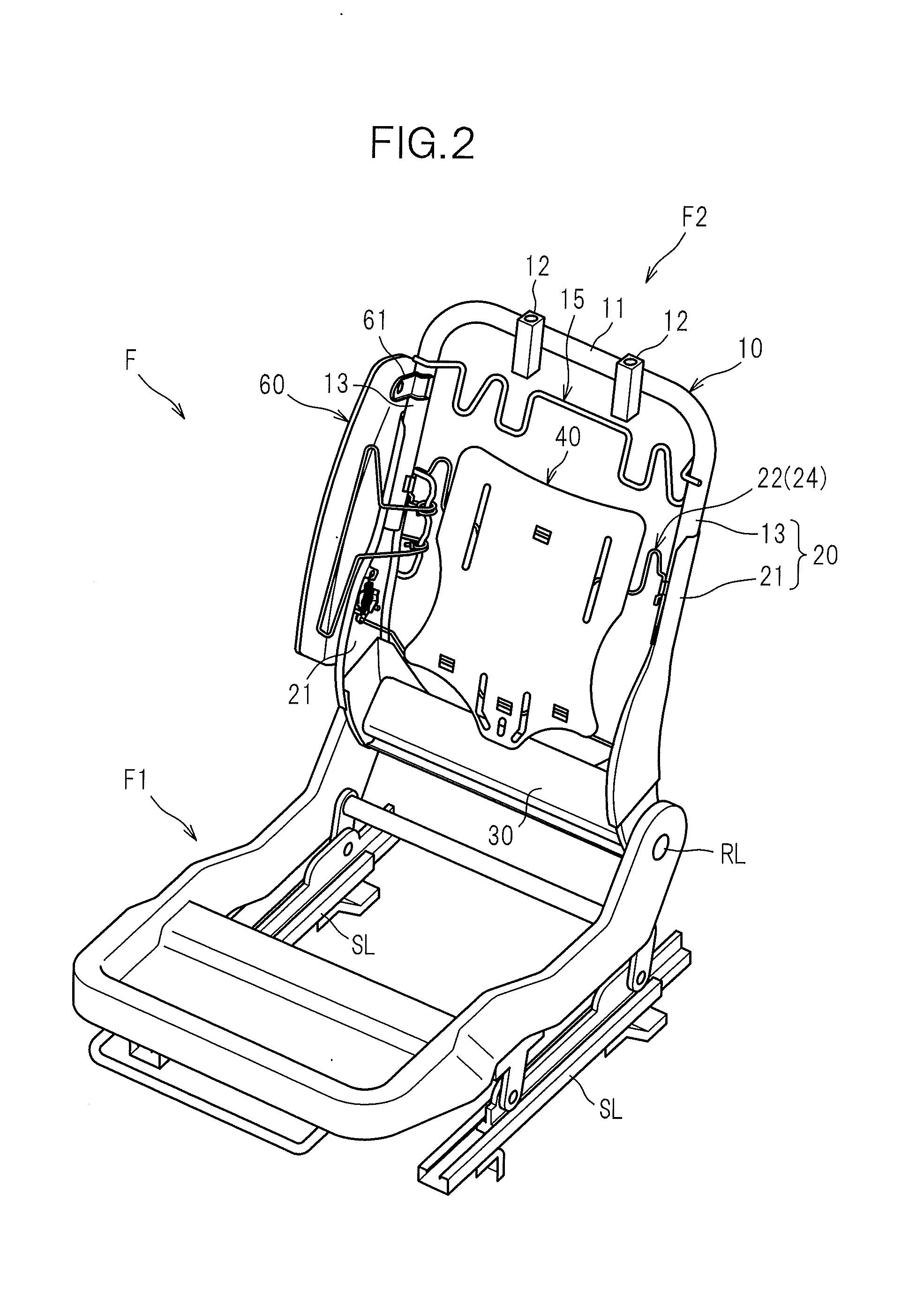
[0052]The seat cushion S1 and the seat back S2 incorporate a seat frame F as shown in FIGS. 2 and 3. This seat frame F comprises a seat cushion frame Fl which constitutes a frame of the seat cushion S1 and a seat back frame F2 which constitutes a frame of the seat back S2. The headrest S3 incorporates a headrest frame (not shown) which constitutes its frame.

[0053]The seat cushion frame F1 shown in FIG. 2 is installed, for example, on a floor...


PUM


Abstract

A seat back pad 70 has a groove 73 for tucking a skin material therein, formed at borders between a central portion 71 and side portions 72. A hole (slot hole 74) is formed in a bottom of the groove 73 along the groove 73. A tuck-in wire 76 for tucking the skin material in includes a plurality of tuck-in portions 76A provided along the groove 73, and a connecting portion (detour portion 76B) detouring around the hole and connecting the tuck-in portions 76A. With this configuration, when an upper body of an occupant P subsides into a seat back S2 in a rear-end collision of a vehicle, the central portion 71, defined by the groove 73 as a border, is easily and sufficiently moved rearward relative to the left and right side portions 72. Furthermore, the tuck-in wire 76 is not exposed through the hole, and thus adhesion between the seat back pad 70 and the tuck-in wire 76 can be improved.

Description

TECHNICAL FIELD[0001]The present invention relates to a vehicle seat such as a car seat, and particularly to a vehicle seat configured to absorb a shock given to a neck of an occupant in a rear-end collision.BACKGROUND ART[0002]In a rear-end collision of a car that occurs when a rear end of your car is struck by another car or when a rear end of your car which is being reversed strikes another car or a construct, a head of an occupant seated on a seat cushion of a car seat would largely tilt back by inertia, and in reaction thereto, the neck of the occupant would likely be given a large shock. With this in view, the car seat is commonly provided with a headrest for receiving the head of the occupant from a back side so as to absorb a shock given to the neck of the occupant in a rear-end collision of the car.[0003]Herein, an occupant seated on a seat cushion and driving a car is, in many cases, postured in an in-seat position with a head slightly apart from the headrest to the front,...

Claims


Application Information

Patent Timeline
IPC IPC(8): B60N2/42
CPCB60N2/4228B60N2/42709B60N2/42745B60N2/643B60N2/70B60N2/7094B60N2/68B60N2/64
Inventor ADACHI, TAKAMASAMATSUZAKI, TSUTOMUYAMAGUCHI, MASAYUKI
Owner TS TECH CO LTD
Learn More