Communication system, communication method and network management apparatus

Inactive Publication Date: 2013-10-17
HITACHI LTD
View PDF2 Cites 7 Cited by
  • Summary
  • Abstract
  • Description
  • Claims
  • Application Information

AI Technical Summary

Benefits of technology

[0010]The communication service provided by an MPLS-TP network provides a subject including a company as the user with a service for communicating the important data. For this reason, the reliability for reducing a service

Problems solved by technology

However, even if the standby path other than the active path is opened in advance to have the active path and the standby path in a communicable state, there is a problem in that the service cannot be continued by switching the active path to the standby path when faults occur simultaneously in the active path and the standby path on the occasion of the wide-area disaster.
However, there is a problem of an increase in load on the network management apparatus for performing the recovery processing from a large number of communication path faults t

Method used


Image

  • Communication system, communication method and network management apparatus
  • Communication system, communication method and network management apparatus
  • Communication system, communication method and network management apparatus

Examples


Example

[0040]A first embodiment of this invention is described below by referring to the accompanying drawings.

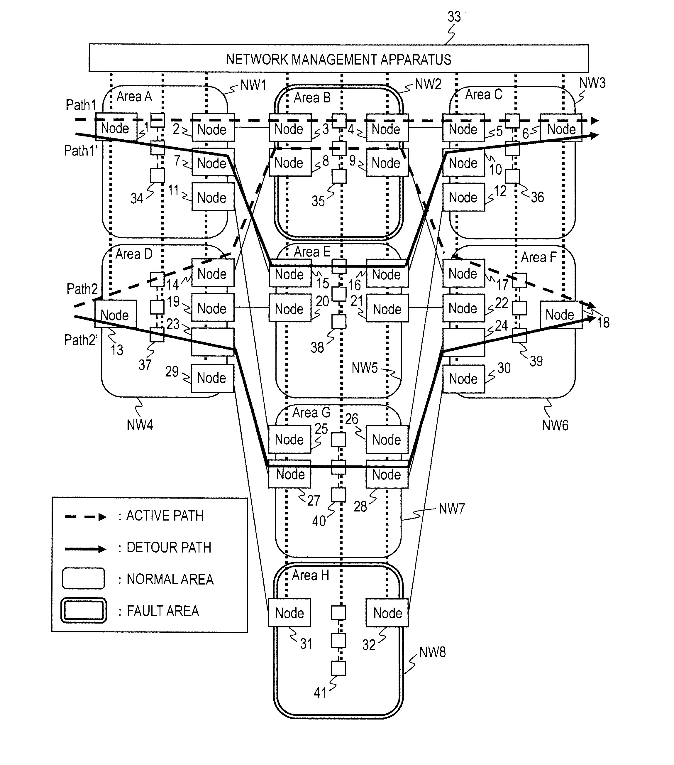
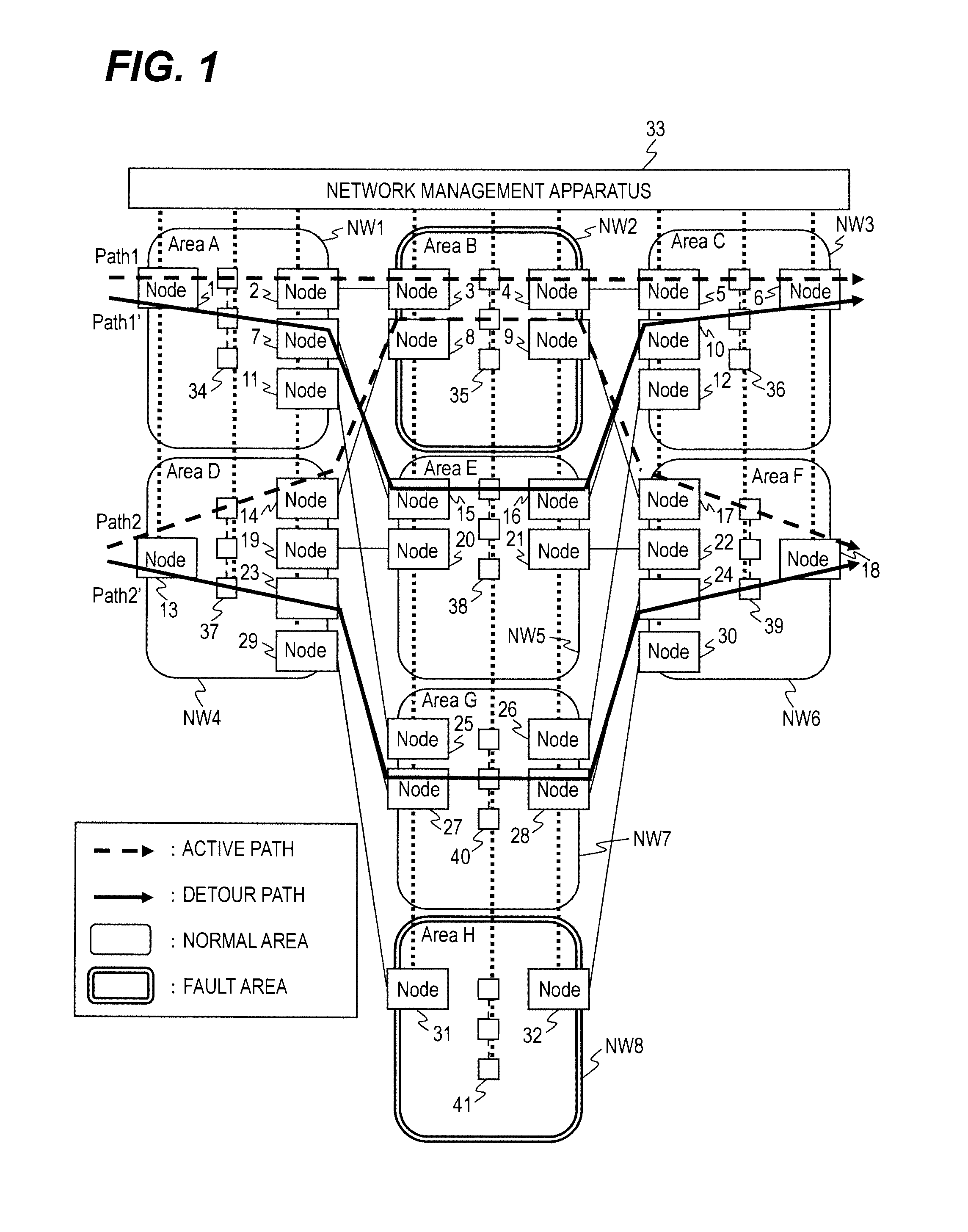
[0041]FIG. 1 is a block diagram illustrating a communication system according to the first embodiment of this invention.

[0042]The communication system illustrated in FIG. 1 includes a bandwidth guarantee network and a network management apparatus 33. The bandwidth guarantee network includes a plurality of nodes 1 to 32 and node groups 34 to 41. Each of the nodes 1 to 32 is a network device (node). Each of the node groups 34 to 41 includes a plurality of network devices (nodes). The node according to this embodiment is a computer having functions such as a switch or a router.

[0043]An administrator of the bandwidth guarantee network manages the nodes 1 to 32 and the node groups 34 to 41 which are included in the bandwidth guarantee network by classifying the nodes 1 to 32 and the node groups 34 to 41 into a plurality of areas A to H (NW 1 to NW8). Each of the areas A to H (NW1 to NW...

Example

[0169]A second embodiment of this invention is described below with reference to the accompanying drawings by focusing on differences from the first embodiment. The second embodiment has a feature of dividing the areas of a bandwidth guarantee network according to this embodiment in a plurality of tiers.

[0170]FIG. 14 is a block diagram illustrating a communication system in a low tier according to the second embodiment of this invention.

[0171]The communication system illustrated in FIG. 14 includes the bandwidth guarantee network and the network management apparatus 33 in the same manner as in the first embodiment. Further, FIG. 14 illustrates the communication system obtained when the network management apparatus 33 determines that the area B (NW2) and the area E (NW5) are the fault areas. In the second embodiment, the areas illustrated in FIG. 14 are referred to as areas in a tier 1.

[0172]Path1 and Path2 of FIG. 14 are the paths for the communication data of the end user in the sa...


PUM


Abstract

In an example of the invention, network devices are classified into areas. Each of the areas includes edge nodes. A network management apparatus retains fault information including values each indicating whether or not a fault has occurred in each of the areas, retains detour path information including values indicating edge nodes, values indicating alternative areas to the areas and priorities assigned to the alternative areas, identifies, when determined that a fault has occurred in a first area based on the fault information, an alternative area to the first area based on the detour path information, determines, when determined that the fault has not occurred in the identified alternative area, the identified alternative area as a second area through which the active path passes, determines two edge nodes included in the second area, and detect network devices through which the active path passes between the two edge nodes.

Description

CLAIM OF PRIORITY[0001]The present application claims priority from Japanese patent application JP2011-222683 filed on Oct. 7, 2011, the content of which is hereby incorporated by reference into this application.BACKGROUND OF THE INVENTION[0002]An amount of information distributed in an intranet has been increasing year by year, and importance of communication services for companies have been growing increasingly. In view of the above-mentioned situation, carriers provide companies as users with a bandwidth guarantee service for laying a communication network for coupling intra-company local area networks (LANs) arranged in a plurality of locations to one another and reserving a bandwidth for each company.[0003]Examples thereof that are being introduced include a communication system to which a multi protocol label switching-transport profile (MPLS-TP) is applied. The MPLS-TP realizes a bandwidth guarantee by establishing an end-to-end path for which a bandwidth is reserved in advan...

Claims


Application Information

Patent Timeline
IPC IPC(8): H04L12/24H04L45/24H04L45/42H04L45/247
CPCH04L41/0654H04L41/0659
Inventor FUJIHIRA, KENJITAKASE, MASAYUKIUDA, TETSUYA
Owner HITACHI LTD
Why Eureka
Try Eureka