Routing system

a routing system and routing device technology, applied in the field of routing systems, can solve the problems of reducing the service interrupt time in the routing device, and shortening the judgment period

Inactive Publication Date: 2008-03-25
FUJITSU LTD
View PDF15 Cites 20 Cited by
  • Summary
  • Abstract
  • Description
  • Claims
  • Application Information

AI Technical Summary

Benefits of technology

[0035]According to the present invention, the service interrupt time depends not on the transmission period of the registration request in the mobile node but on the period of the judgment by the monitoring unit. The service interrupt time can be reduced by shortening the period of the judgment by the monitoring unit in the routing device according to the present invention. Moreover, the load exerted by the monitoring unit onto the active system routing is smaller than the load exerted onto the active system routing device by the mobile node's transmitting the registration request. Hence, the monitoring unit can execute monitoring with the period shorter than the period with which the registration request is executed. Accordingly, the service interrupt time in the routing device can be reduced.
[0036]Further, according to the present invention, the active system routing device and the standby system routing device take the synchronization among the contents stored on the storage units by executing the registration request forwarding processes. Therefore, the load of the communications between the active system routing device and the standby system routing device can be made smaller than in the case of taking the synchronization by sending the contents stored on the storage units. Accordingly, the active system routing device and the standby system routing device are excellent of the synchronization among the contents stored on the storage units, and the service interrupt time in the routing device can be reduced.

Problems solved by technology

The redundancy technology has, however, the following problems.

Method used


Image

  • Routing system
  • Routing system
  • Routing system

Examples


first embodiment

[0066][[Outline Architecture of System]]

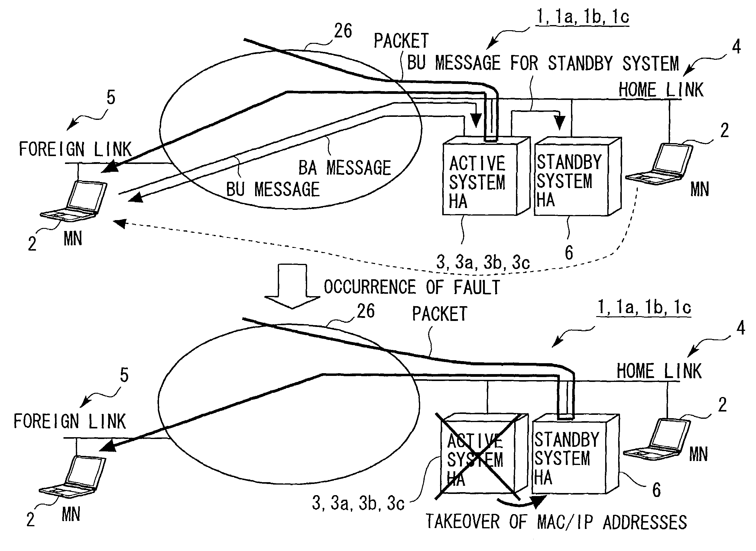
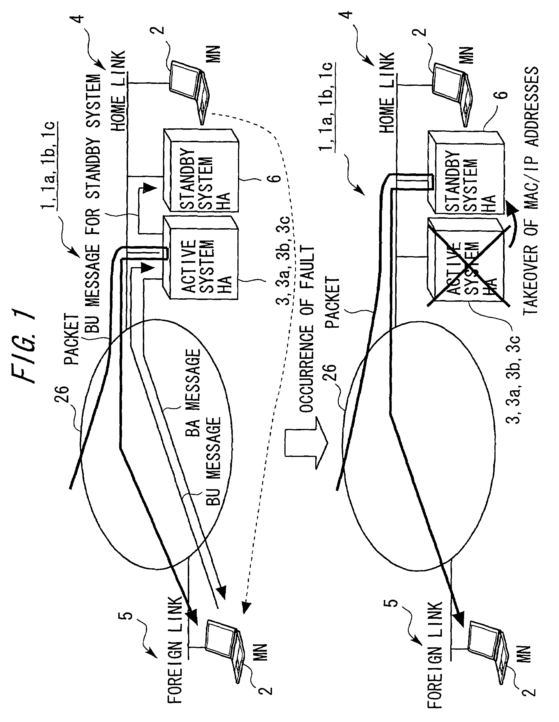
[0067]FIG. 1 is a view showing an outline architecture of a packet routing system 1 in a first embodiment of the present invention. The packet routing system 1 includes a mobile node 2, an active system home agent (HA) 3, a home link 4, a foreign link 5, a standby system home agent (HA) 6 as a standby system HA, and a network 26 that connects the home link 4 and the foreign link 5 so as to be communicable with each other.

[0068]According to the packet routing system 1, the active system HA 3 forwards a BU (Binding Update) message received from the mobile node 2 to the standby system HA 6, thereby scheming to take synchronization among contents of BC (Binding Cache) tables. An architecture of each of the components will hereinafter be explained.

[0069]

[0070]The mobile node 2 is configured by use of a mobile information processing device. This type of information processing device is exemplified such as a PDA (Personal Digital Assistant), a cellul...

second embodiment

[0129][[System Architecture]]

[0130]Next, a packet routing system 1a in a second embodiment of the present invention will be discussed (see FIG. 1). The packet routing system 1a includes substantially the same components as those of the packet routing system 1 in the first embodiment. To be specific, the packet routing system 1a includes the mobile node 2, an active system home agent (HA) 3a, the home link 4, the foreign link 5, the standby system HA 6, and the network 26 that connects the home link 4 and the foreign link 5 so as to be communicable with each other.

[0131]According to the packet routing system 1a, the active system HA 3a, with a priority flag attached to the BU message, judges based on this priority flag whether the BU message received from the mobile node 2 is forwarded or not. The following discussion on the packet routing system 1a will be focused on only different components from the packet routing system 1.

[0132]

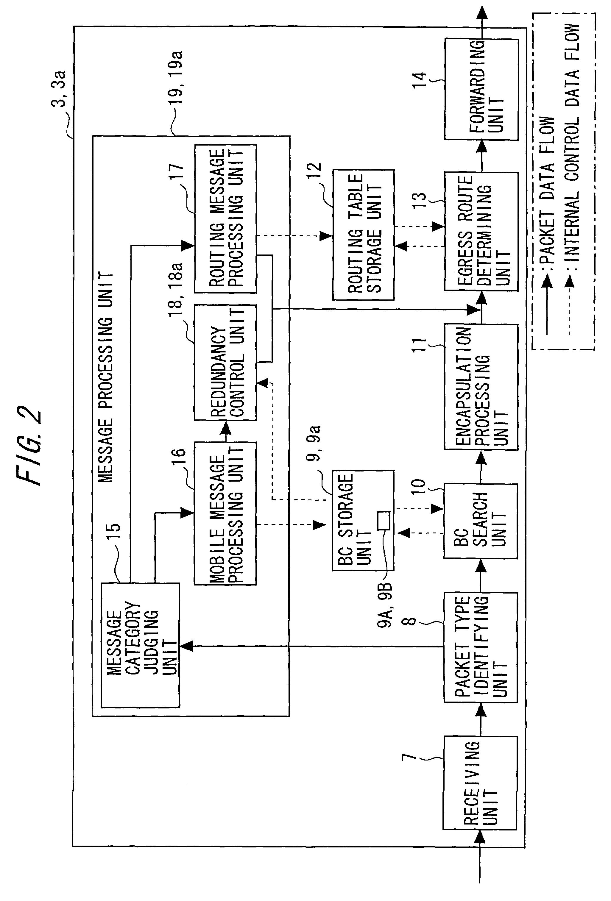
[0133]The active system HA 3a includes a BC storage ...

third embodiment

[0150][[System Architecture]]

[0151]Next, a packet routing system 1b in a third embodiment of the present invention will be discussed (see FIG. 1). The packet routing system 1b includes substantially the same components as those of the packet routing system 1 in the first embodiment. To be specific, the packet routing system 1b includes the mobile node 2, an active system home agent (HA) 3b, the home link 4, the foreign link 5, the standby system HA 6, and the network 26 that connects the home link 4 and the foreign link 5 so as to be communicable with each other.

[0152]According to the packet routing system 1b, the active system HA 3b sets statistic information mapping to the BU message, and judges based on the statistic information whether the BU message received from the mobile node 2 is forwarded or not. The following discussion on the packet routing system 1b will be focused on only different components from the packet routing system 1 in the first embodiment.

[0153]

[0154]FIG. 10 ...


PUM


Abstract

An active system routing device, upon receiving a location registration request sent from a mobile node, forwards the received location registration request to a standby system routing device. The standby system routing device stores a home address and a care-of address of the mobile node in a way that maps these addresses to each other based on the location registration request received from the active system routing device, monitors a status of the active system routing device and, upon detecting a fault of the active system routing device, executes switching over the self-device to an active system.

Description

BACKGROUND OF THE INVENTION[0001]1. Field of the Invention[0002]The present invention relates to a routing system for receiving a datagram (packet) addressed to a mobile node and forwarding the received datagram to a relevant mobile node on the basis of a home address and a care-of address.[0003]2. Description of the Related Art[0004]Standardization of Mobile IPv6 (Internet Protocol version 6) as a protocol related to the mobile node (MN) in an IP network, has been promoted over the recent years. Mobile IPv6 is defined as a protocol that enables the mobile node to seamlessly perform communications even when changing its location of a network link (visiting a foreign network).[0005]FIG. 28 is a diagram showing an outline architecture of a system P1 utilizing Mobile IPv6. The system P1 utilizing Mobile IPv6 will be explained referring to FIG. 28.[0006]The system P1 includes a mobile node P2, a home agent (HA) P3, a home link (home network) P4, a foreign link P5 and a network P6 that c...

Claims


Application Information

Patent Timeline
Patent Type & Authority Patents(United States)
IPC IPC(8): H04J3/14H04L1/00H04W40/34G06F11/00H04B7/26H04L45/586H04L45/85H04W24/00H04W24/04H04W80/04
CPCH04L45/02H04L45/586H04W8/12H04W40/02H04W80/04
Inventor WATANABE, NAOTOSHI
Owner FUJITSU LTD
Why Eureka
Try Eureka