
Distributed blade server system, management server and switching method

a blade server and blade technology, applied in the field of communication technologies, can solve the problems of low system reliability and low blade reliability, and achieve the effect of improving system reliability

Active Publication Date: 2014-06-24
HUAWEI TECH CO LTD
View PDF15 Cites 3 Cited by
  • Summary
  • Abstract
  • Description
  • Claims
  • Application Information

AI Technical Summary

Benefits of technology

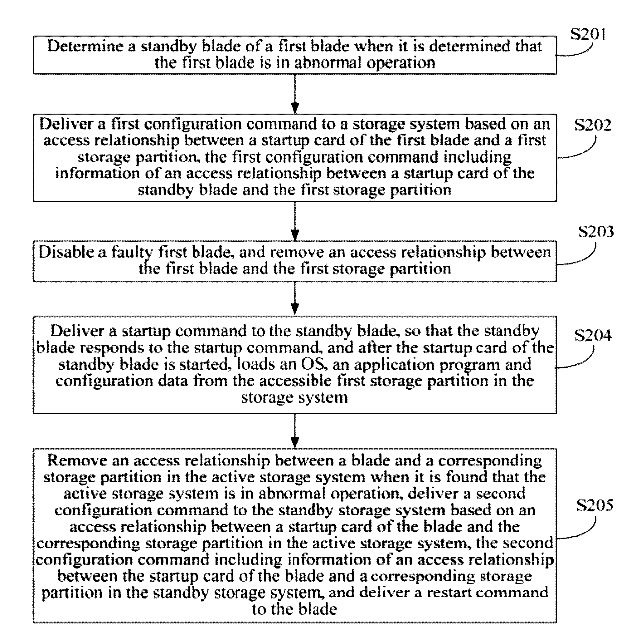
The present invention provides a distributed blade server system with a management server that can quickly switch to a standby blade when there is a fault in the main blade. The management server detects the abnormal operation of a blade and sends a command to the storage system to configure an access relationship between the standby blade and the first storage partition. The standby blade then loads the necessary operating system, application program, and configuration data from the accessible storage partition and responds to the startup command. This allows for quicker switchover to the standby blade in case of a fault, reducing service interruption time and improving system reliability.

Problems solved by technology

In the implementation of the present invention, the inventor finds that though the blade server subsystem requires low power consumption, the density of blades is high, and in a high-density deployment environment, the reliability of blades is lower than that of tower and rack servers, and spare blades may not be replaced quickly; and in a distributed system, the reliability of nodes deployed on the blade server is lower than that of nodes deployed on a minicomputer, as a result, a system reliability is low.

Method used


Image

  • Distributed blade server system, management server and switching method
  • Distributed blade server system, management server and switching method
  • Distributed blade server system, management server and switching method

Examples


Embodiment Construction

[0037]In order to make the objectives, technical solutions, and advantages of the present invention clearer, the technical solutions of the present invention are clearly described below through specific embodiments with the accompanying drawings. It is obvious that the embodiments to be described are a part rather than all of the embodiments of the present invention. All other embodiments obtained by persons skilled in the art based on the embodiments of the present invention without creative effects shall fall within the protection scope of the present invention.

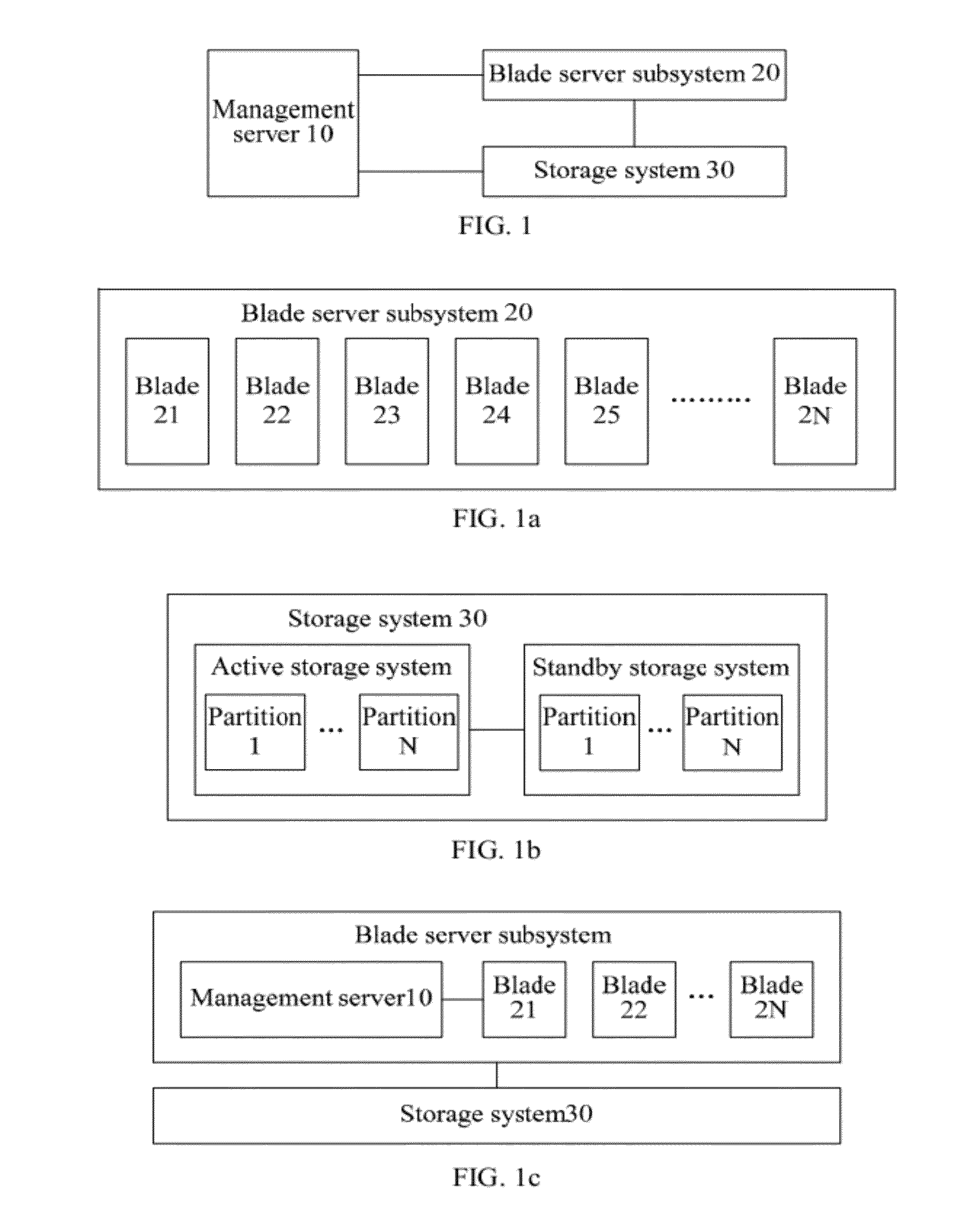
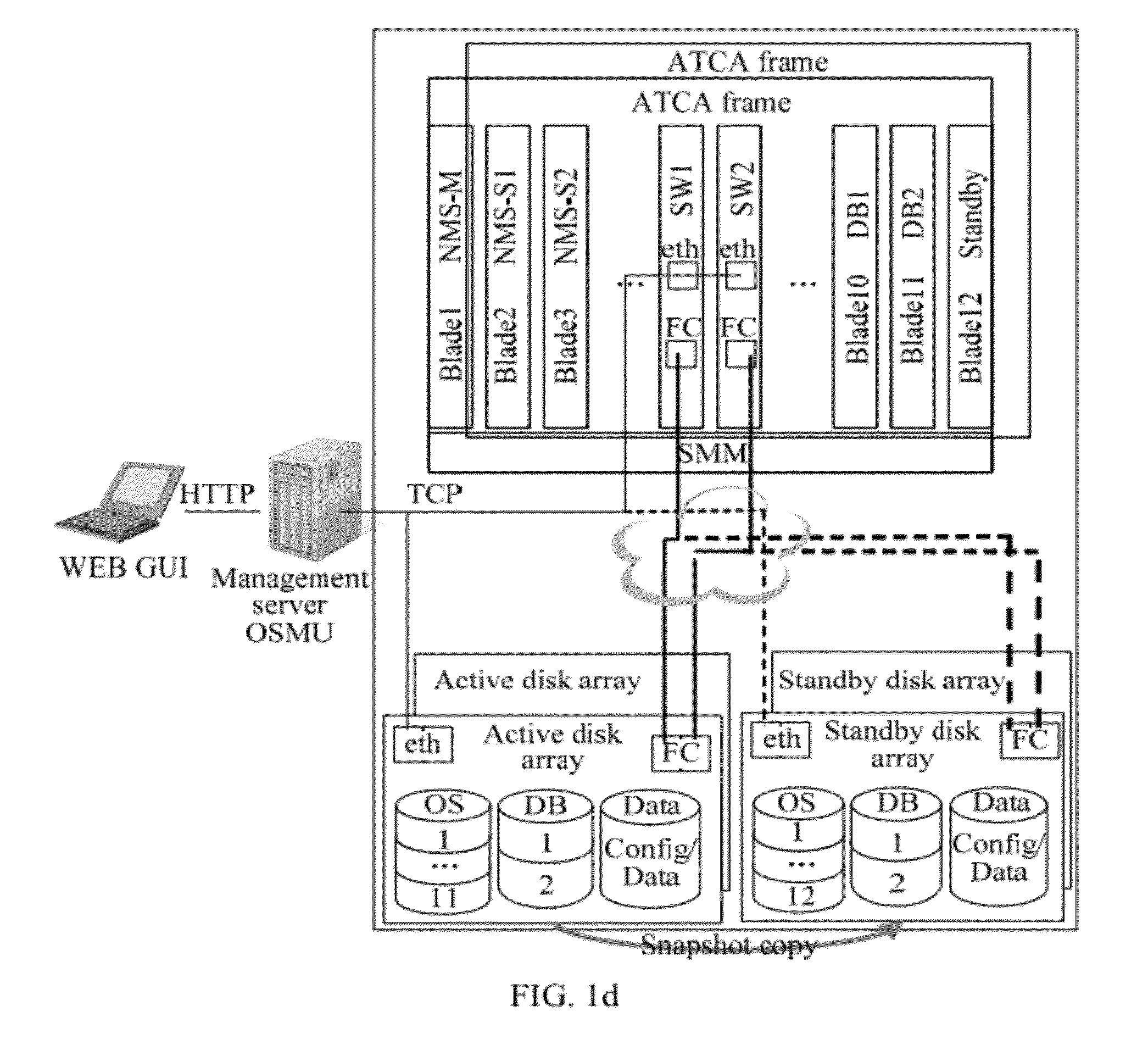
[0038]FIG. 1 is a schematic diagram of a logical structure of a distributed blade server system according to an embodiment of the present invention. As shown in FIG. 1, the distributed blade server system according to the embodiment of the present invention includes: a management server 10, a storage system 30, and a blade server subsystem 20 (as shown in FIG. 1a) including multiple blades 21, 22, . . . , and 2N, and the ma...


PUM


Abstract

A distributed blade server system, a management server and a switching method are provided. The method includes: determining a standby blade of a first blade when it is determined that the first blade is in abnormal operation; delivering, based on an access relationship between a startup card of the first blade and a first storage partition, a first configuration command to a storage system, the first configuration command including information of an access relationship between a startup card of the standby blade and the first storage partition, so that the storage system configures the access relationship between the startup card of the standby blade and the first storage partition; and delivering a startup command to the standby blade.

Description

CROSS-REFERENCE TO RELATED APPLICATIONS[0001]This application is a continuation of International Application No. PCT / CN2011 / 075368, filed on Jun. 7, 2011, which claims priority to Chinese Patent Application No. 201010565746.9, filed on Nov. 30, 2010, both of which are hereby incorporated by reference in their entireties.FIELD OF THE INVENTION[0002]The present invention relates to the field of communications technologies, and in particular, to a distributed blade server system, a management server and a switching method.BACKGROUND OF THE INVENTION[0003]A blade server subsystem is characterized by high computing capability, space saving, centralized management and being easy to extend. Compared with a conventional rack system and a tower server system, the blade server subsystem may help enterprises to reduce the costs of power supply, heat dissipation and storage space, and as a result, a blade server has been used due to advantages with respect to cost efficiency.[0004]The blade ser...

Claims


Application Information

Patent Timeline
Patent Type & Authority Patents(United States)
IPC IPC(8): G06F11/00
CPCG06F11/2033G06F11/2071G06F11/2046G06F11/2025G06F11/2038G06F11/2028G06F11/2069G06F11/2082
Inventor WU, ZHAOHUIJIANG, YOUYU
Owner HUAWEI TECH CO LTD
Learn More