Manipulator and polishing mechanism thereof

a technology of manipulator and polishing mechanism, which is applied in the direction of grinding drive, grinding head, manufacturing tools, etc., can solve the problems of workpieces being easily fractured and the work efficiency is relatively low

Inactive Publication Date: 2013-10-17
FU TAI HUA IND SHENZHEN +1
View PDF21 Cites 44 Cited by
  • Summary
  • Abstract
  • Description
  • Claims
  • Application Information

AI Technical Summary

Problems solved by technology

However, such de-burring polishing process is labor-consuming, the work efficiency ...

Method used


Image

  • Manipulator and polishing mechanism thereof
  • Manipulator and polishing mechanism thereof
  • Manipulator and polishing mechanism thereof

Examples


Embodiment Construction

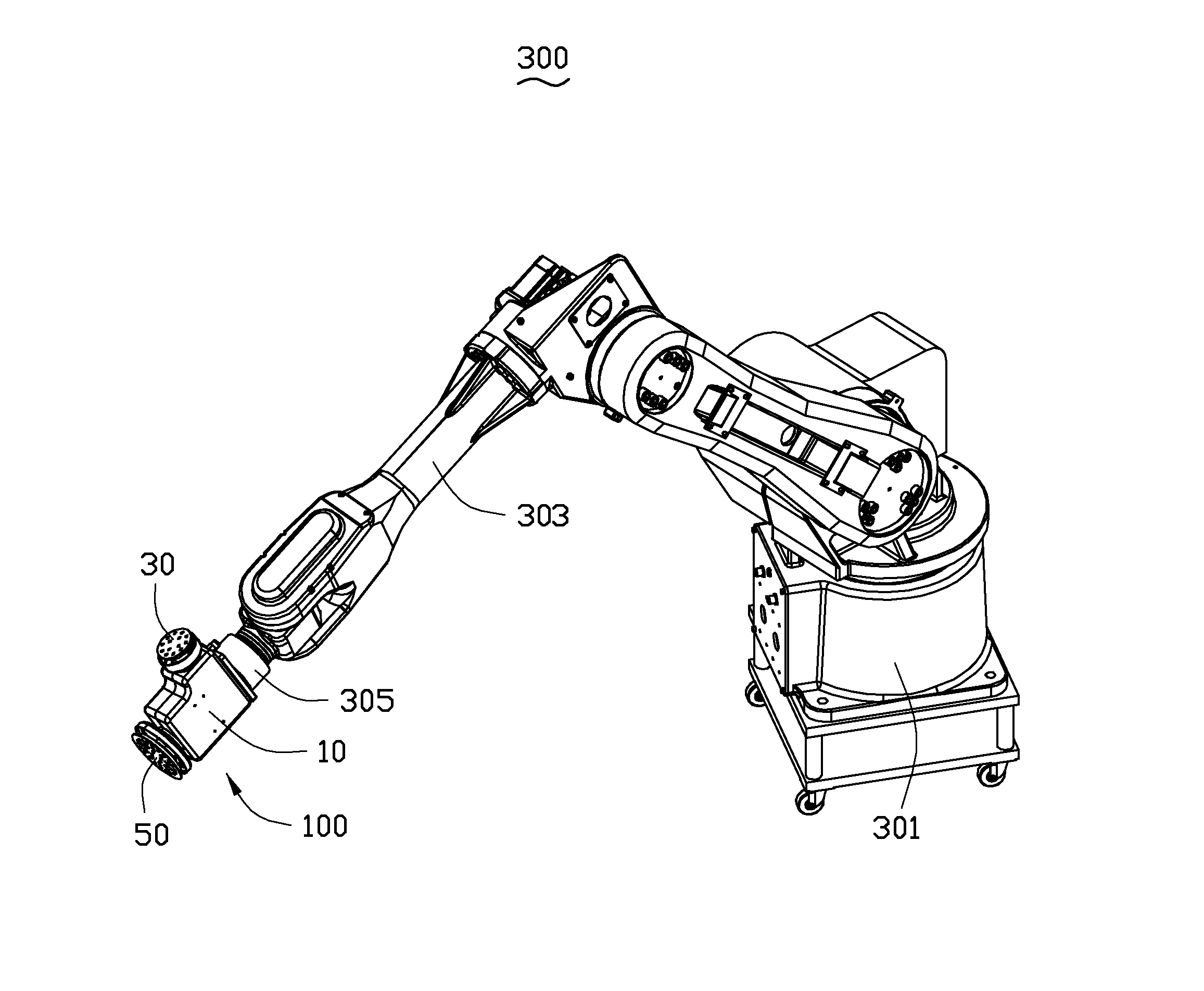
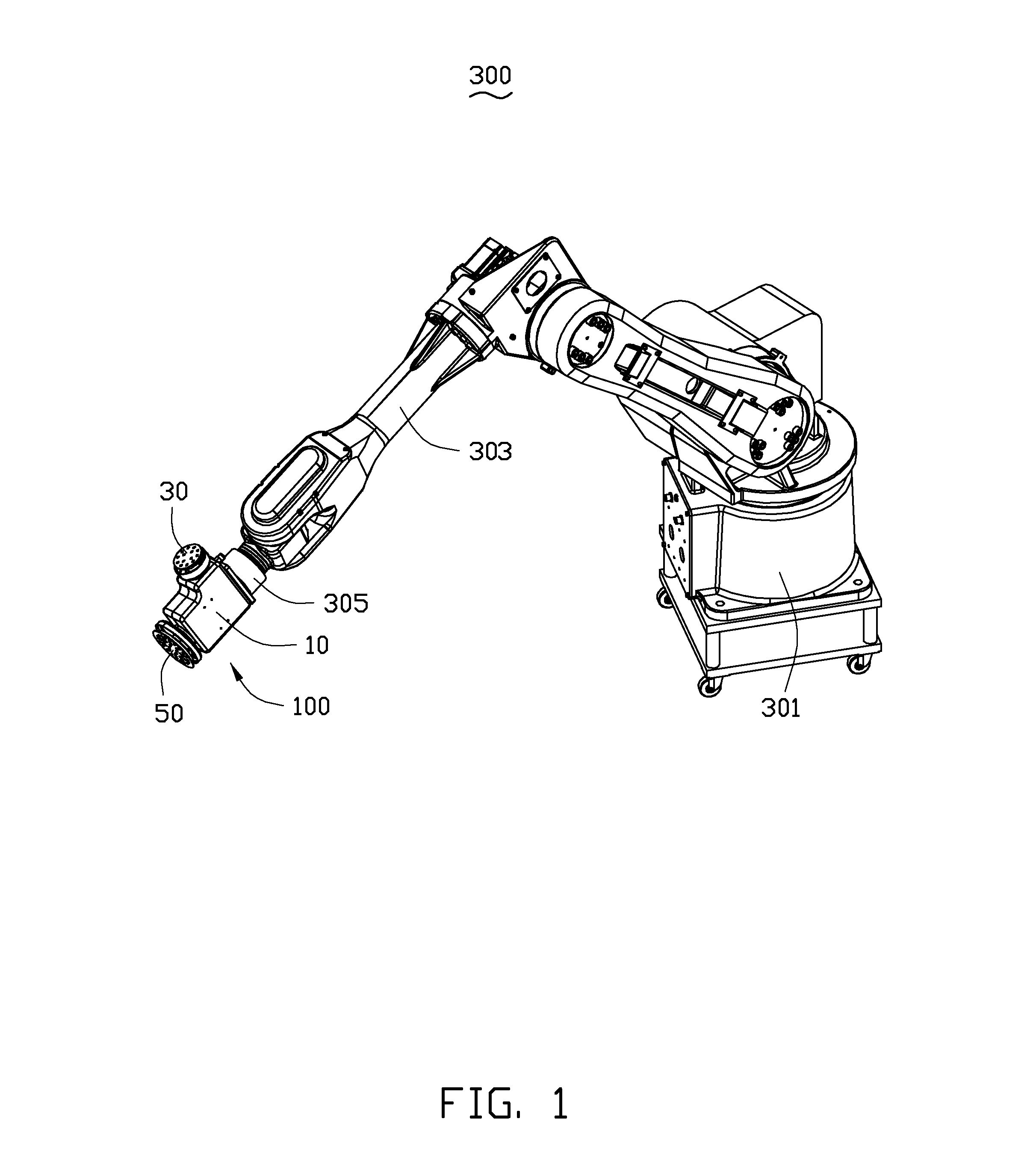
[0012]Referring to FIGS. 1 and 2, an embodiment of a manipulator 300 includes a controlling seat 301, a robot arm assembly 303 and a polishing mechanism 100. The robot arm assembly 303 is rotatably connected to the controlling seat 301. The polishing mechanism 100 is mounted on an end of the robot arm assembly 303 away from the controlling seat 301. The polishing mechanism 100 is electrically connected to the controlling seat 301. The polishing mechanism 100 is capable of polishing a plurality of surfaces of a workpiece 200 (see FIG. 5) when driven by the robot arm assembly 303. In the embodiment, as shown in FIG. 5, the workpiece 200 is turned over for polishing, and includes a curved base wall 201, a sidewall 203 extending along a periphery of the base wall 201. A top surface 205 is formed on the sidewall 203 away from the base wall 201.

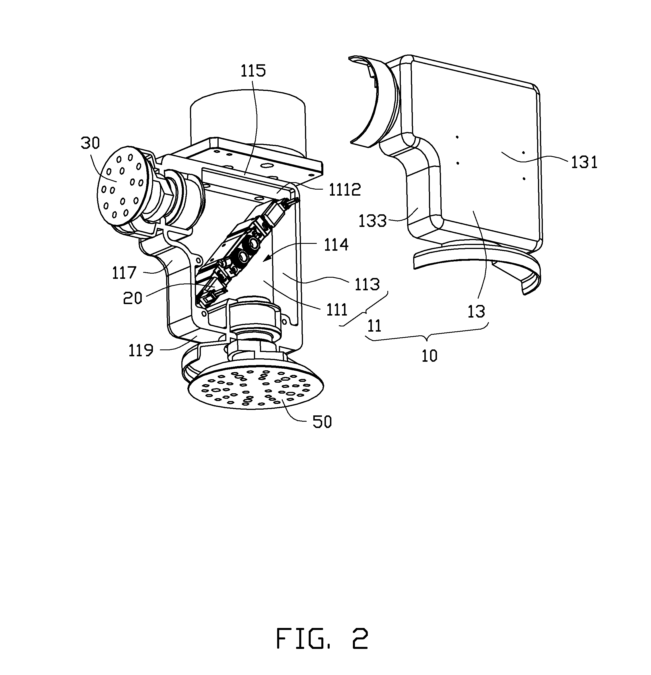
[0013]The polishing mechanism 100 includes a housing 10, a pair of magnetic valves 20, a first polishing assembly 30 and a second polishing assemb...


PUM


Abstract

A manipulator includes a controlling seat, a robot arm assembly and a polishing mechanism. The robot arm assembly is rotatably connected to the controlling seat; and the polishing mechanism is mounted on the robot arm assembly. The polishing mechanism includes a housing with a first mounting portion and a second mounting portion, a pair of magnetic valves mounted in the housing and electrically connected to the controlling seat, a first polishing assembly partially received in the first mounting portion, and a second polishing assembly partially received in the second mounting portion. The first polishing assembly and the second polishing assembly define an angle therebetween and are respectively connected to the pair of magnetic valves, such that the pair of magnetic valves controls the first and the second polishing assembly respectively to polish one or more workpiece. The present invention further discloses a polishing mechanism of the manipulator.

Description

BACKGROUND[0001]1. Technical Field[0002]The present disclosure relates to manipulators, and more particularly, to a manipulator for de-burring and a polishing mechanism of the manipulator.[0003]2. Description of Related Art[0004]Burrs on metallic workpieces produced by fabrication processes are typically removed manually. An operator polishes the metallic workpiece with a sandpaper to remove the burrs. However, such de-burring polishing process is labor-consuming, the work efficiency is relatively low and the workpiece may be fractured easily during the polishing process.[0005]Therefore, there is room for improvement in the art.BRIEF DESCRIPTION OF THE DRAWINGS[0006]The components in the drawings are not necessarily drawn to scale, the emphasis instead placed upon clearly illustrating the principles of the present disclosure. Moreover, in the drawings, like reference numerals designate corresponding parts throughout the several views.[0007]FIG. 1 is an isometric view of an embodimen...

Claims


Application Information

Patent Timeline
IPC IPC(8): B24B27/00B24B41/00B24B47/14
CPCB24B27/0076B24B47/14B24B41/002B24B27/0038B25J11/0065
Inventor GUAN, HONG-LIHE, CHANG-XUELIANG, MING
Owner FU TAI HUA IND SHENZHEN
Why Eureka
Try Eureka